ENGINE
Cylinder Head
12/05
BY Service Manual
5-29
© 2009 Yanmar Marine International
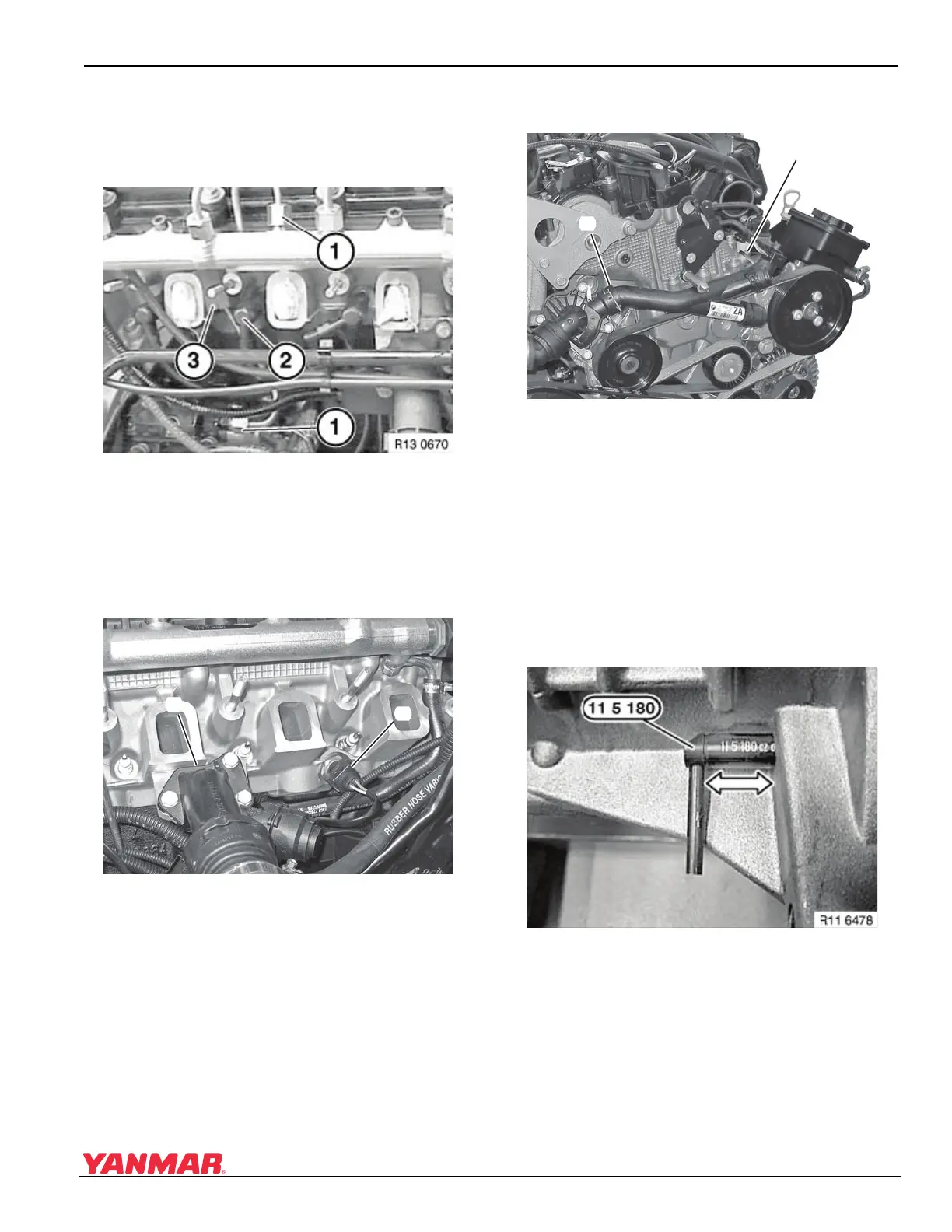
8. Install high-pressure pump-to-fuel rail line
(Figure 5-41, (1)).
4BY2 Engines: Install rubber mount
(Figure 5-41, (3)).
Figure 5-41
Figure 5-41
9. Install the glow plugs (Figure 5-41, (2)).
10. Install high-pressure fuel rail. See Remove and
Install Fuel Rail on page 6-20.
11. Connect harness connector to temperature
sensor (Figure 5-42, (2)).
Figure 5-42
Figure 5-42
12. Install coolant branch fitting (Figure 5-42, (1))
with a new seal and tighten bolts.
13. Connect oil cooler return pipe (Figure 5-43, (2))
to thermostat housing.
Figure 5-4 3
Figure 5-43
14. Install bolt (Figure 5-43, (1)).
15. Install fuel injectors. See Install Fuel Injector on
page 6-13. Connect high-pressure lines using
special tool OEM No. 13 5 020. See Remove
and Install High-Pressure Fuel Lines on
page 6-14.
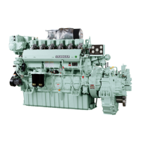
16. Rotate crankshaft using the crankshaft
dampener bolt until No. 1 cylinder is at TDC.
Secure flywheel using flywheel holding tool
OEM No. 11 5 180 (Figure 5-44).
Figure 5-4 4
Figure 5-44
0003767
(
1
)
(
2
)
0003766
(
1
)
(
2
)