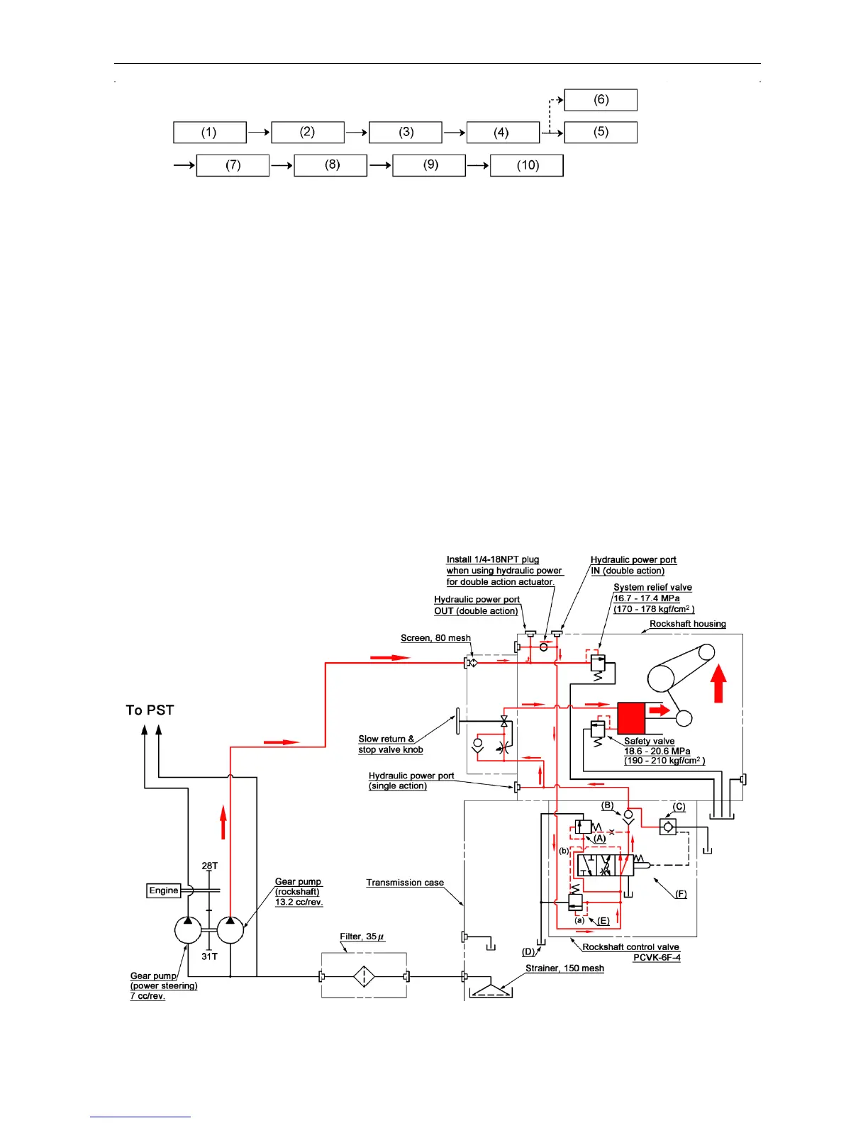
Circuit in the control valve
The unload valve is applied with the pilot pressure (a) and (b) at
an equal level. It is closed by means of the spring and the oil
pressure from the pump increases to cause the oil to go through
the throttle in the spool to the cylinder after opening the check
valve.
This is the process of a rapid pressure increase. The flow control
valve and mechanical check valve are both closed.
When the hydraulic lift rises, a feedback takes place to make the
spool return to the neutral position and the main spool throttle
makes part of oil flow through the tank after opening the flow
control valve. The remaining oil flows to the cylinder to eliminate a
shock at the upper dead point.
 Loading...