20 support@yardistrystructures.com
Hardware
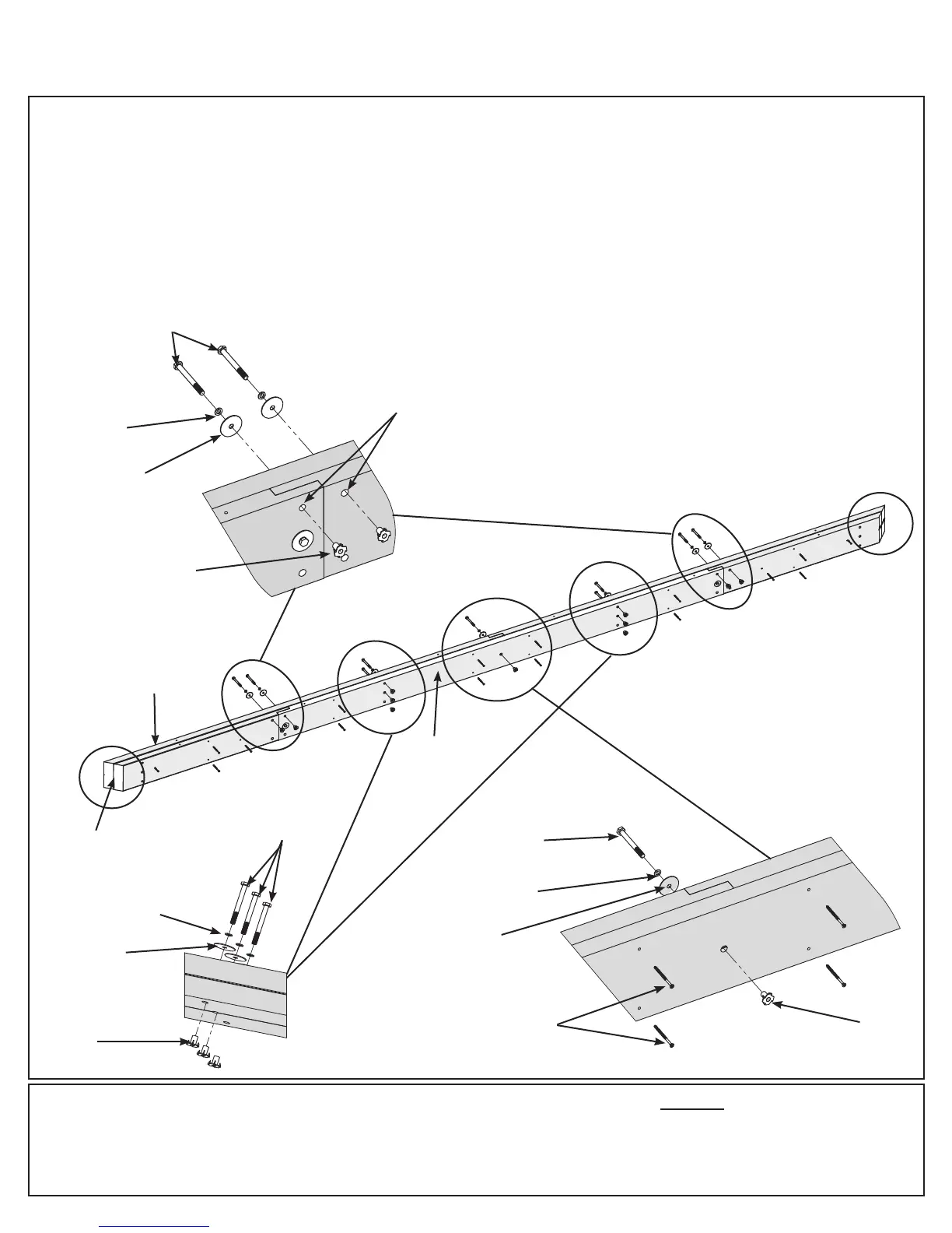
F: Place one Outer Beam Assembly and one Inside Beam Assembly together so the beam assembly ends are
ush and the angled ends match. Bolt heads must be on the outside of both beam assemblies. Match the bolt
holes in each assembly then loosely attach with eleven 5/16 x 3” Hex Bolts (with 5/16” lock washer, 1/4-5/16”
large washer and 5/16” t-nut). The bolts at each end must go in the top holes. (g. 4.7, 4.8, 4.9 and 4.10)
G: Secure assemblies with 16 #8 x 2-1/2” Wood Screws then tighten bolts. (g. 4.7 and 4.9)
H: Repeat Step F and G to make a second Long Beam Assembly.
Step 4: Long Beam Assembly
Part 3
Flush
#8 x 2-1/2” Wood
Screws (x 16 per
assembly)
Fig. 4.8
Fig. 4.9
Outer Beam
Assembly
Inside Beam
Assembly
Notice orientation
of angled ends
Fig. 4.7
32 x #8 x 2-1/2” Wood Screw
22 x 5/16 x 3” Hex Bolt
(5/16” lock washer, 1/4-5/16” large washer, 5/16” t-nut)
5/16”
T-nut
1/4-5/16”
Large Washer
5/16 x 3”
Hex Bolt
5/16” Lock
Washer
Use the
top holes
5/16”
T-nut
1/4-5/16”
Large Washer
5/16 x 3”
Hex Bolt
5/16” Lock
Washer
Fig. 4.10
5/16 x 3”
Hex Bolt
5/16” Lock
Washer
5/16”
T-nut
1/4-5/16”
Large Washer