21 support@yardistrystructures.com
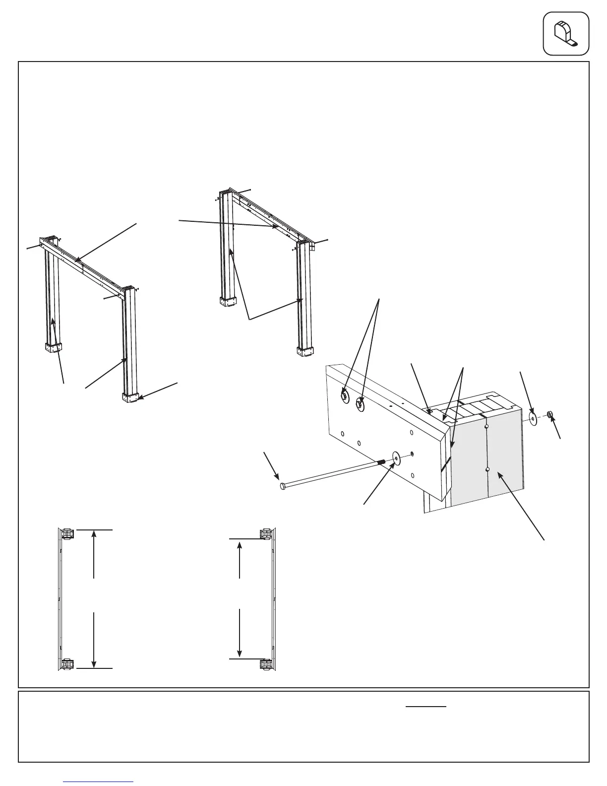
Step 5: Frame Assembly and Anchoring
Part 1
Fig. 5.1
A: On a hard, at surface place one Short Beam Assembly against the outside of two Post Assemblies, on the
short side, ush to the tops and outside corners. Attach Beam to Post, through the middle hole, with one 3/8 x 12-
1/2” Hex Bolt (with two 3/8” large washers and one 3/8” lock nut) per Post. (g. 5.1 and 5.2)
The distance from the outside of one Post Assembly to the outside of the second Post Assembly should be 10’ 10-
3/8”. See g. 5.3 for accurate positioning of Posts.
B: Repeat Step A for second Short Beam Assembly. These will now be referred to as Short Side Assemblies.
Fig. 5.2
Hardware
4 x 3/8 x 12-1/2” Hex Bolt (3/8” large washer x 2, 3/8” lock nut)
Fig. 5.3
3/8” Large
Washer
3/8 x 12-1/2”
Hex Bolt
Plinth
Notice bolts at
top of board
Short Beam
Assembly
3/8” Lock
Nut
Short Side
10’ 10-3/8”
Post to Post
9’ 8-1/2”
Plinth to Plinth
Post Assembly
Flush
Post
Assembly
Post
Assembly
3/8” Large
Washer
3.31 m
2.96 m