22 support@yardistrystructures.com
Step 5: Frame Assembly and Anchoring
Part 2
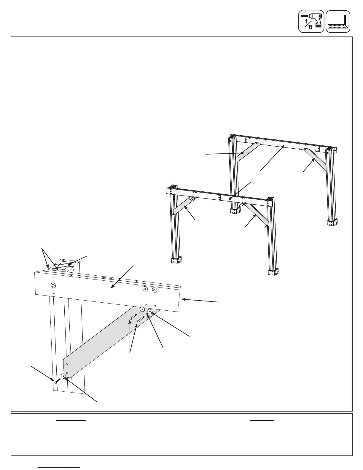
Note: The bevelled ends on each gusset should always face away from the wood it is attaching to.
C: Make sure each Short Side Assembly is square, top of Beam Assembly is ush to the top of the Post Assembly
and angle of Beam Assembly is ush to the side of the Post Assemlby, then facing one Short Beam Assembly from
the outside place one (786) Straight Gusset Right on the right hand side so the top ts tight to the Short Beam
Assembly and the bottom ts tight to the Post Assembly. Attach gusset to Short Beam Assembly with two 5/16
x 3-3/4” Hex Bolts (with 5/16” lock washer, 1/4-5/16” large washer and 5/16” t-nut). Pre-drill with a 1/8” drill bit
then attach gusset to Post Assembly, through the bottom hole, with one 5/16 x 3” Lag Screw (with 1/4-5/16” large
washer). (g. 5.4 and 5.5)
D: Repeat Step C on the left hand side with one (787) Straight Gusset Left. (g. 5.4 and 5.5)
E: Repeat Steps C and D for second Short Side Assembly.
Fig. 5.4
2 x (786) Straight Gusset Right
2 x (787) Straight Gusset Left
HardwareWood Parts
4 x 5/16 x 3” Lag Screw (1/4-5/16” large washer)
8 x 5/16 x 3-3/4” Hex Bolt
(5/16” lock washer, 1/4-5/16” large washer, 5/16” t-nut)
Fig. 5.5
Post
Assembly
Short Side
Assembly
5/16”
T-nut
(hidden)
5/16” Lock
Washer
5/16 x 3”
Lag Screw
1/4-5/16”
Large Washer
5/16 x 3-3/4”
Hex Bolt
(787) Straight
Gusset Left
Short Beam
Assembly
1/4-5/16”
Large Washer
(786) Straight
Gusset Right
(787) Straight
Gusset Left
(786) Straight
Gusset Right
Flush