23 support@yardistrystructures.com
Hardware
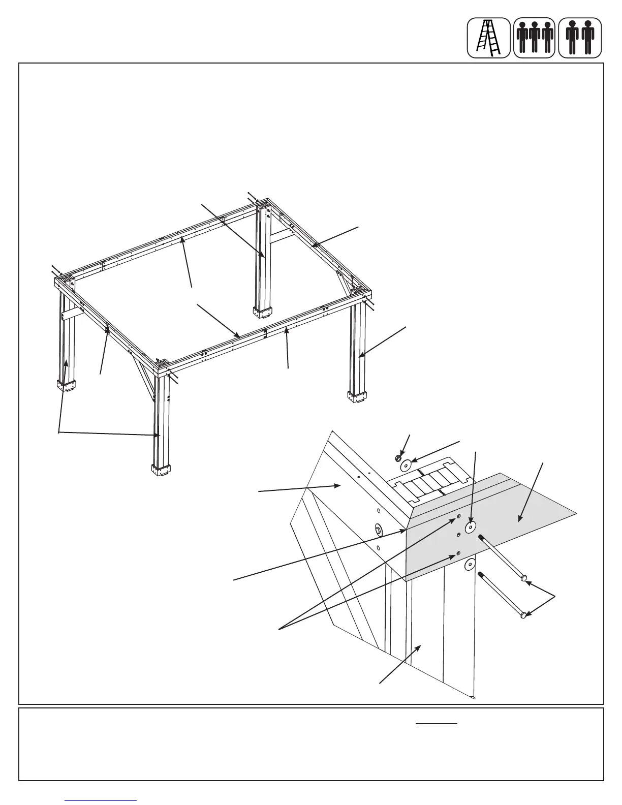
Fig. 5.6
Long Beam
Assembly
Short Side
Assembly
Step 5: Frame Assembly and Anchoring
Part 3
x 4
8 x 3/8 x 9-1/2” Hex Bolt (3/8” large washer x 2, 3/8” lock nut)
F: Move your Short Side Assemblies to the nal location. Make sure the ground is at and level before continuing
assembly.
G: With helpers stand up Short Side Assemblies then place one Long Beam Assembly against the outside of two
Post Assemblies, ush to the tops and outside corners and tight to Short Beam Assembly. Attach Long Beam
Assembly to Post Assembly through the top and bottom holes with two 3/8 x 9-1/2” Hex Bolts (with two 3/8” large
washers and one 3/8” lock nut) per Post Assemby. Repeat for the second Long Beam Assembly on the opposite
side. (g. 5.6 and 5.7)
Long Beam
Assembly
Short Side
Assembly
Post
Assembly
Post
Assembly
Post
Assembly
3/8” Large
Washer
3/8 x 9-1/2”
Hex Bolt
3/8”
Lock Nut
Short Beam
Assembly
Long Beam
Assembly
Flush
and tight
Fig. 5.7
Post
Assembly
Use
these
holes