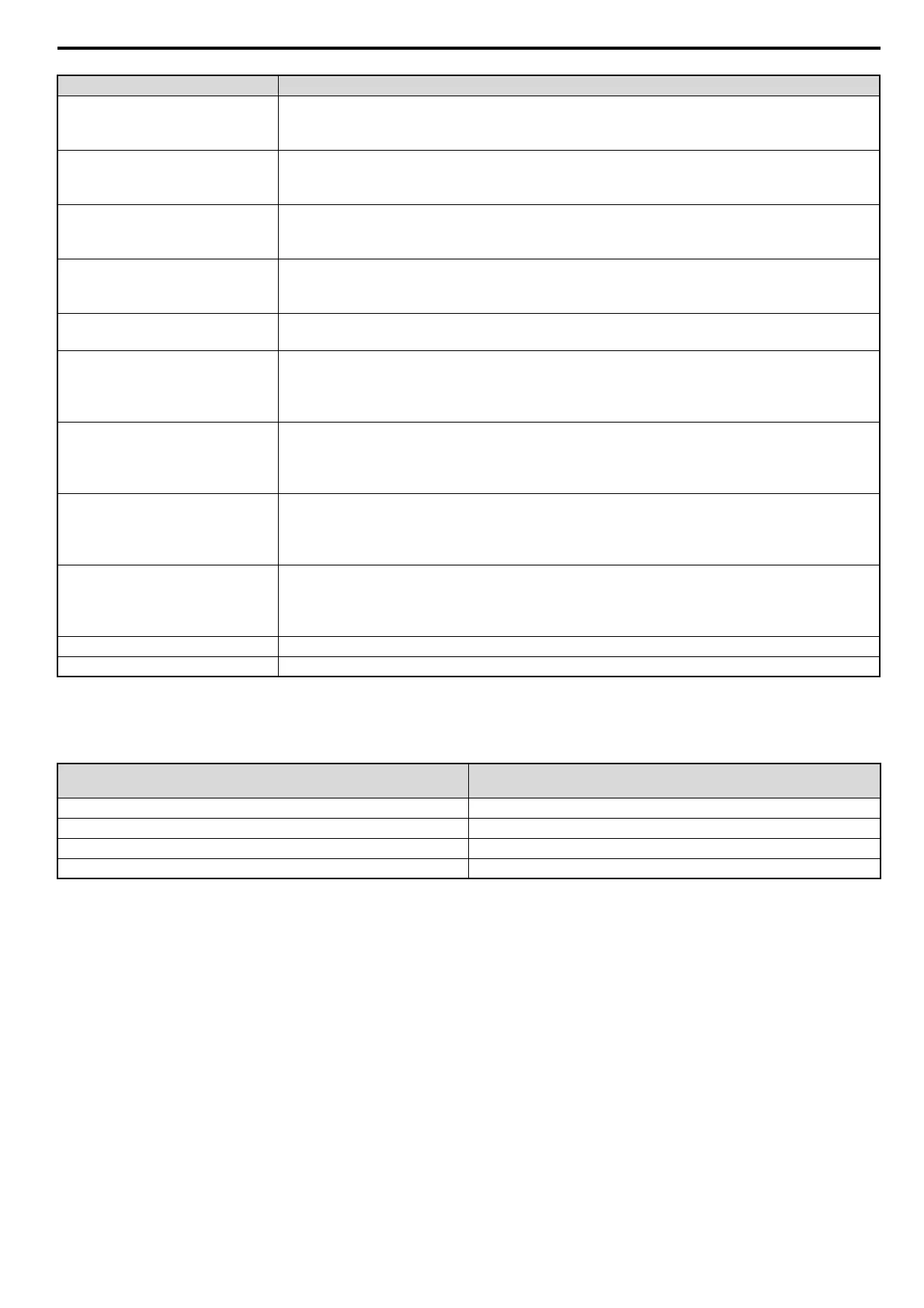
8 Output Assemblies (Drive Consumes)
YASKAWA ELECTRIC SIEP C730600 43B 1000-Series Option SI-N3 Technical Manual 29
Note: This is a paired assembly (105/155).
Table 9 Function Code Decode Table
Note: Refer to the MEMOBUS/Modbus Data Table in the drive Technical Manual for a list of monitor data using the MEMOBUS/
Modbus message area.
Multi-Function Input 7
Terminal S7 Function Input
0: Terminal S7 Function (H1-07) OFF
1: Terminal S7 Function (H1-07) ON
Multi-Function Input 8
Terminal S8 Function Input
0: Terminal S8 Function (H1-08) OFF
1: Terminal S8 Function (H1-08) ON
External Fault
External Fault EF0
0: No External Fault (EF0)
1: External Fault (EF0)
Fault Reset
Fault Reset
0: No Fault Reset
1: Fault Reset
Function Code
MEMOBUS/Modbus Function Code
Refer to Function Code Decode Table on page 29.
Multi-Function Digital Output
Terminal M1/M2
0: M1/M2 OFF
1: M1/M2 ON
This function is enabled only when H2-01 is set to F.
Multi-Function Photocoupler 1
Terminal P1
0: P1 OFF
1: P1 ON
This function is enabled only when H2-02 is set to F.
Multi-Function Photocoupler 2
Terminal P2
0: P2 OFF
1: P2 ON
This function is enabled only when H2-03 is set to F.
Speed Reference
Speed Command
Sets drive speed reference
Unit depends on o1-03.
Unit is not affected by Speed Scale SS.
Register Number MEMOBUS/Modbus Register Number
<1>
Register Data MEMOBUS/Modbus Register Data
<1> Register numbers 0x0001, 0x0002, and 0x0009 are disabled.
Function Code
High Byte - Low Byte
MEMOBUS/Modbus Function
0 0 No Operation
1 0 Read Register
0 1 Write Register
1 1 No Operation
Name Description
 Loading...


