10 Attachment
YASKAWA TOMPC71061753A YASKAWA AC Drive GA500 Installation and Operation Instruction 269
Note:
• The recommended wire gauges are based on drive continuous current ratings with 75 °C (167 °F) 600 V class 2 heat-
resistant indoor PVC wire. Assume these conditions:
–Ambient temperature: 40 °C (104 °F) maximum
–Wiring distance: 100 m (3281 ft) maximum
–Normal Duty rated current value
• Refer to the instruction manual for each device for recommended wire gauges to connect peripheral devices or options
to terminals +1, +2, -, B1, and B2. Contact Yaskawa or your nearest sales representative if the recommended wire
gauges for the peripheral devices or options are out of the range of the applicable gauges for the drive.
Notes on Wiring the Main Circuit Terminal Block
Read these notes before you wire the main circuit terminal block.
• Use UL-Listed, vinyl-coated insulated copper wires for operation with a continuous
maximum permitted temperature of 75 °C at 600 V.
• Remove all unwanted objects that are near the terminal block connections.
• Remove the insulation from the connection wires to the wire stripping lengths shown in the
manual.
• Do not use bent or crushed wires. Remove the damaged end of the wire before you use it.
Incorrect connections can cause death or serious injury from fire.
• Do not solder stranded wire. Soldered wire connections can become loose over time and
cause unsatisfactory drive performance.
• If you use stranded wire, make sure that all of the wire strands are in the connection. Also, do
not twist the stranded wire too much. Incorrect connections can cause death or serious injury
from fire.
• Put the wire all the way into the terminal block. Remove the insulation from the wire to the
recommended wire stripping length to fit the wire with insulation in the plastic housing.
• Use a torque driver, torque ratchet, or torque wrench for the screws. A slotted driver or a hex
tool will be necessary to wire the screw clamp terminal. Use applicable tools as specified by
the recommended conditions in the product manual.
• If you use power tools to tighten the terminal screws, use a low speed setting (300 to 400 r/
min). Failure to obey can cause damage to the terminal screws.
• Wire gauges on existing drive models to be replaced may not match wire gauge ranges on
new drives. Refer to the drive manuals for correct wire sizes.
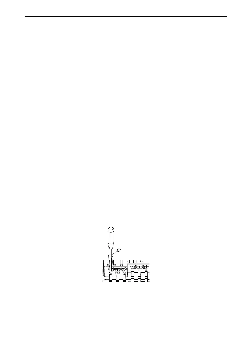
• Do not tighten the terminal screws at an angle of 5 degrees or more. Failure to obey can cause
damage to the terminal screws.
Figure 10.2 Permitted Angle
• Put the bit all the way into the hex socket to tighten the hex socket cap screw.
• When you tighten slotted screws, hold the straight-edge screwdriver perpendicularly to the
screw. Make sure that you align the end of the straight-edge screwdriver with the screw
groove.

 Loading...


