59
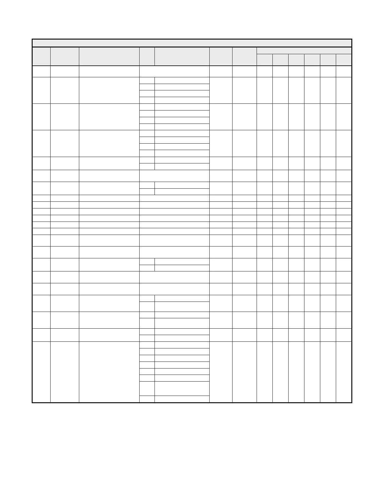
Table 4.9 “F” Parameters
Access Level
Name
Address Description Data
Range Unit Default
During
Run
V/f
V/f
w/PG
OLV
FV OLV2
F1-01
0380h PG Pulses/Revolution 0 ~ 60000 Pulses 1 Pulse
1024
Pulses
Q Q
0 Ramp to Stop
1 Coast to Stop
2 Fast-Stop (C1-09)
F1-02
0381h
PG Feedback Loss Selection
(PGO)
3 Alarm Only
1 1 A A
0 Ramp to Stop
1 Coast to Stop
2 Fast-Stop (C1-09)
F1-03
0382h
PG Overspeed Selection
(OS)
3 Alarm Only
1 1 A A A
0 Ramp to Stop
1 Coast to Stop
2 Fast-Stop (C1-09)
F1-04
0383h
PG Speed Deviation
Selection
(DEV)
3 Alarm Only
1 3 A A A
0 Forward = C.C.W.
F1-05
0384h PG Rotation Selection
1 Forward = C.W.
1 0 A A
F1-06
0385h
PG Output Ratio
(PG-B2 Only)
1 ~ 132 1 1 A A
0 Disabled
F1-07
0386h
PG Accel/Decel ASR
Integral Selection
1 Enabled
1 0 A
F1-08
0387h PG Overspeed Level 0 ~ 120 % 1 % 115 % A A A
F1-09
0388h PG Overspeed Time 0.0 ~ 2.0 Sec 0.1 Sec 1.0 Sec A A A
F1-10
0389h PG Deviation Level 0 ~ 50 % 1 % 10 % A A A
F1-11
038Ah PG Deviation Time 0.0 ~ 10.0 Sec 0.1 Sec 0.5 Sec A A A
F1-12
038Bh PG Gear Teeth 1 0 ~ 1000 1 0 A
F1-13
038Ch PG Gear Teeth 2 0 ~ 1000 1 0 A
F1-14
038Dh
PG Feedback Loss Detection
Time
0.0 ~ 10.0 Sec 0.1 Sec 2.0 Sec A A
F1-21
03B0h
PG Pulses/Revolution
(Motor 2)
0 ~ 60000 Pulses 1 Pulse
1024
Pulses
Q Q
0 Forward = C.C.W.
F1-22
03B1h
PG Rotation Selection
(Motor 2)
1 Forward = C.W.
1 0 Q Q
F1-23
03B2h
PG Gear Teeth 1
(Motor 2)
0 ~ 1000 1 0 A
F1-24
03B3h
PG Gear Teeth 2
(Motor 2)
0 ~ 1000 1 0 A
0 Disabled
F1-25
03B4h
Hardware PG Feedback Loss
(PGOH)
Channel 1 (PG-T2/Z2 Only)
1 Enabled
1 1 A A
0 Disabled
F1-26
03B5h
Hardware PG Feedback Loss
(PGOH)
Channel 2 (PG-Z2 Only)
1 Enabled
1 1 A A
0 3-channel Individual
F2-01
038Fh
AI-14B Option Kit
Input Selection
1 3-channel Summed
1 0 A A A A A
0 BCD 1%
1 BCD 0.1%
2 BCD 0.01%
3 BCD 1 Hz
4 BCD 0.1 Hz
5 BCD 0.01 Hz
6
BCD (5-digit) 0.01 Hz
(DI-16H2 Only)
F3-01
0390h
DI-08/DI-16H2 Option Kit
Input Type Selection
7 Binary
1 0 A A A A A