60
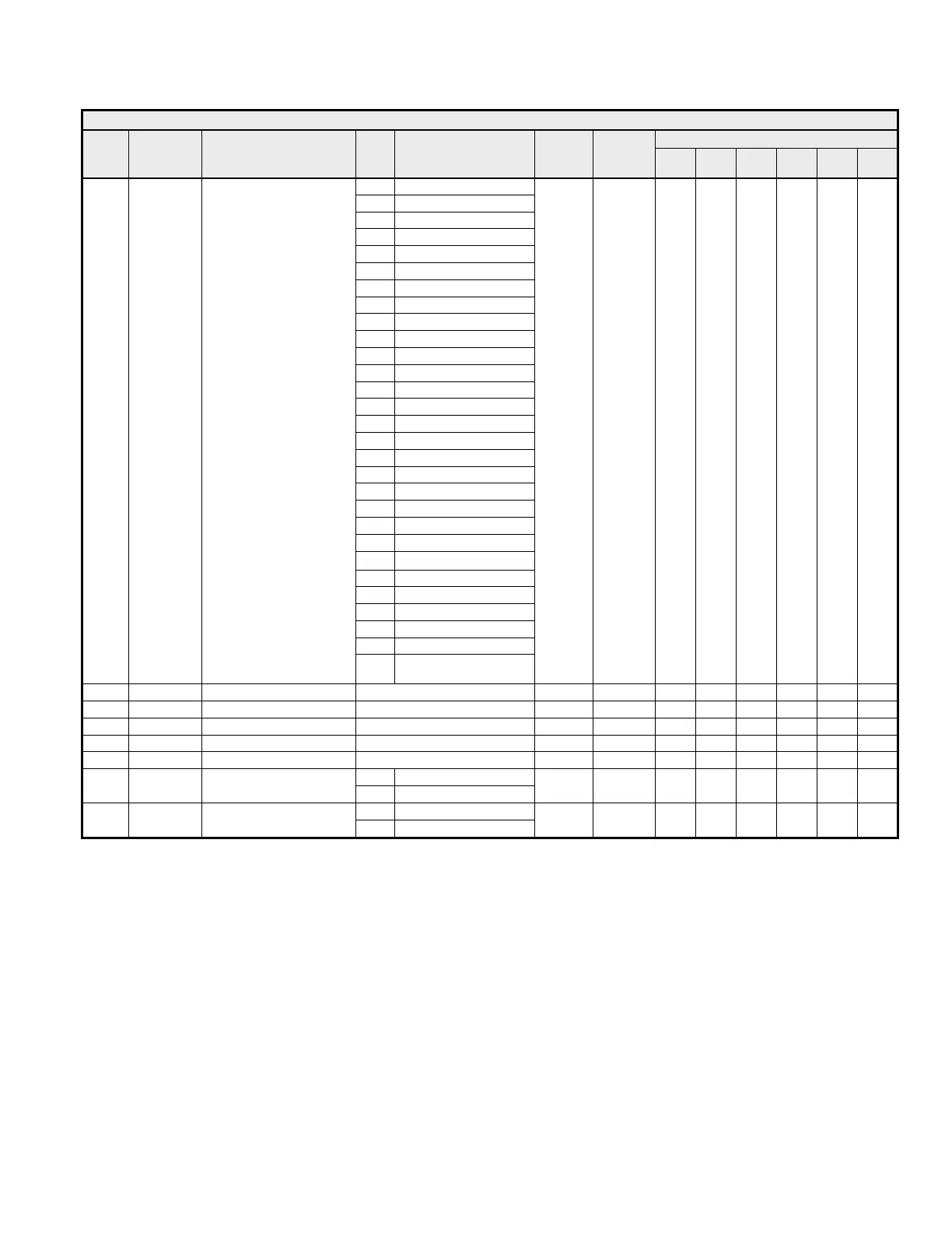
Table 4.9 “F” Parameters
Access Level
Name
Address Description Data
Range Unit Default
During
Run
V/f
V/f
w/PG
OLV
FV OLV2
1 Frequency Reference
2 Output Frequency
3 Output Current
5 Motor Speed
6 Output Voltage
7 DC Bus Voltage
8 Output Power (kW)
9 Torque Reference
15 Terminal A1 Level
16 Terminal A2 Level
17 Terminal A3 Level
18 Motor Secondary Current
19 Motor Excitation Current
20 Soft Starter (SFS) Output
21 ASR Input
22 ASR Output
24 PID Feedback
26 Voltage (Vq) Reference
27 Voltage (Vd) Reference
32 ACR (Iq) Output
33 ACR (Id) Output
36 PID Input
37 PID Output
38 PID Setpoint
42 Estimated Motor Flux
43 Id Compensation Value
44 ASR Output Without Filter
45 Feed Forward Output
F4-01
0391h
AO-08/AO-12 Option Kit
Channel 1 Function Selection
48
Stabilizing Speed at
Regeneration (OLV2)
1 02h - - - - -
F4-02
0392h AO-08/12 Channel 1 Gain 0.0 ~ 1000.0 % 0.1 % 100.0 % R A A A A A
F4-03
0393h AO-08/12 Channel 2 Select
See F4-01 1 03h A A A A A
F4-04
0394h AO-08/12 Channel 2 Gain 0.0 ~ 1000.0 % 0.1 % 50.0 % R A A A A A
F4-05
0395h AO-08/12 Channel 1 Bias -110.0 ~ 110.0 % 0.1 % 0.0 % R A A A A A
F4-06
0396h AO-08/12 Channel 2 Bias -110.0 ~ 110.0 % 0.1 % 0.0 % R A A A A A
0 0-10 VDC
F4-07
0397h
AO-12 Channel 1
Signal Type Selection
1 -10 +10 VDC
1 0 A A A A A
0 0-10 VDC
F4-08
0398h
AO-12 Channel 2
Signal Type Selection
1 -10 +10 VDC
1 0 A A A A A