YASKAWA TOEP YAIQPM 01A iQpump Micro Quick Start Procedure
iQpump Micro
Quick Start Procedure
Page 14
of 31
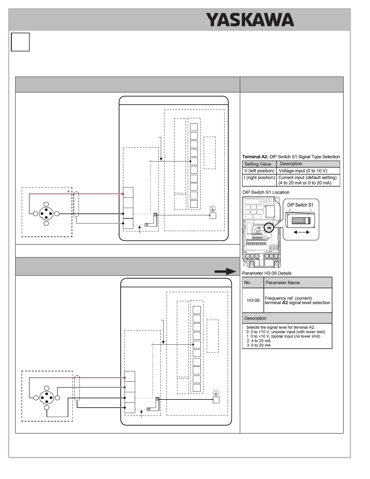
5.17 Connect wiring from customer-supplied transducer to 24V Power Supply.
Refer to Figure 1.6 Transducer (2-Wire) connection or Figure 1.7 Transducer (3-Wire) connection based on the application.
Figure 1.6 (2-Wire) 4 to 20 mA Transducer
Setting DIP Switch S1 for
Terminal A2 Signal Type Selection
Signal Wire (white)
24 V PSU to Drive
A2
24V
AC
FE
24V Power Supply
Shield
SIG
FE
Functional Earth Cable
(Blue)
J2
24V Power Supply
Transducer
Signal 4-20 mA
(typical)
CN1
Terminal
Block
TB1-2
TB1-1
TB2
TB1-3
EG
A2
A1
PC
P2
V+
AM
AC
MP
AC
P1
iQpump Micro Drive
(Earth
Ground)
Internal Circuit
Internal Circuit
iQpump Micro Drive
I/O Terminals
2
4
3
1
N/C
N/C
V+
Output
Example:
Customer supplied
pressure transducer
feedback device
(2-Wire)
Note: Transducer wire colors and numbering may vary depending on feedback device used, consult feedback device
manual.
Figure 1.7 (3-Wire) 0 to 10 V Transducer
Note: Set DIP switch S1 located on drive to V position for use with 0 to 10V transducer.
Signal Wire (white)
24 V PSU to Drive
A2
24V
AC
FE
24V Power Supply
Shield
FE
Functional Earth Cable
(Blue)
J2
24V Power Supply
Transducer
Signal 0-10 Vdc
(typical)
CN1
Terminal
Block
Example:
Customer supplied
pressure transducer
feedback device
(3-Wire)
TB1-2
TB1-1
TB2
TB1-3
EG
A2
A1
PC
P2
V+
AM
AC
MP
AC
P1
iQpump Micro Drive
(Earth
Ground)
Internal Circuit
Internal Circuit
iQpump Micro Drive
I/O Terminals
Supply Common
2
4
3
1
N/C
V+
Output
Com
+
Note: Refer to the iQpump Micro User Manual, (No. TOEPYAIQPM03) to program the iQpump Micro drive for network communication if
required.
Install the 24 V Transducer Power Supply (continued)
5
STEP