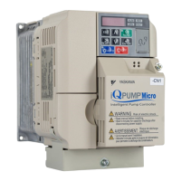
YASKAWA TOEP YAIQPM 01A iQpump Micro Quick Start Procedure
iQpump Micro
Quick Start Procedure
Page 16
of 31
Install the 24 V Transducer Power Supply (continued)
5
STEP
5.21
Connect transducer wiring to the 24V Power Supply terminals using Figure 1.10 as a guide.
Strain Relief
24V
AC
A2
FE
F1
C1
CN5
J2
J1
C3
C2
D1
TB1
20
19
10
9
12
11
2
1
xxxxxxxxxxxxxxx
xxxxxxxxxxxxxxx
Transducer Wiring
Shielded
Transducer Cable
(Customer Supplied)
Preparing Wire
Terminal Ends
E
A
B
D
C
24V FEA2AC
A – Terminal block CN1
B – Avoid fraying wire strands when
stripping insulation from wire. Strip
length 5.5 mm.
C – Single wire or stranded wire
D – Loosen screw to insert wire.
E – Blade depth of 0.4 mm or less
Blade width of 2.5 mm or less
Figure 1.10 24V Power Supply Wiring Guide
NOTICE: Separate transducer wiring from main circuit wiring (terminals R/L1, S/L2, T/L3, B1, B2, U/T1, V/T2, W/T3,
⊖
,
⊕
1,
⊕
2) and other high-power lines. Improper wiring practices could result in drive malfunction due to electrical interference.
NOTICE: Damage to Equipment. Do not tighten screws beyond the specified tightening torque. Failure to comply may damage
the terminal block. Refer to 24V Power Supply Wire Size and Torque Specifications on page 13 for details.
Table 1.17 24V Power Supply Terminal Block CN1
CN1 Terminal Block Terminal No. Terminal Name (Function)
Function (Signal Level)
Default Setting
24V Tranducer Power Supply +20V to +24V Vdc 30 mA
AC Power Supply Common 0 Vdc
A2 Analog input 4-20 mA, 0-20 mA, 0-10 Vdc
FE
Functional Earth Ground for
Shielded Connection

 Loading...


