184 YASKAWA TM.iQp.02 iQpump Drive Programming Manual
H2-02
(continued)
040CH
Terminal M3-M4
Function Selection
Ter m M3 -M 4 Se l
42: Pump Fault
Function Active in hand, auto, pre-charge and thrust mode
Open: No Dedicated Pump Faults are active.
Closed: Dedicated pump fault active (Low Feedback Fault, High
Feedback Fault, Over Cycling Fault, Pump Protection Fault,
Thermostat Fault, Low Water Fault, Ext. Pump Fault).
0 to 42 41 Programming
63
Analog Inputs
H3-02
0411H
Terminal A1 Gain Setting
Terminal A1 Gain
Sets the speed command when 10 V is input, as a percentage of the
maximum output frequency (E1-04).
0.0 to
1000.0
100.0% Programming
70
H3-03
0412H
Terminal A1 Bias Setting
Terminal A1 Bias
Sets the speed command when 0 V is input, as a percentage of the
maximum output frequency (E1-04).
–100.0 to
+100.0
0.0% Programming
70
H3-08 0417H
Terminal A2 Signal
Level Selection
Term A2 Signal
Selects the signal level of terminal A2.
0: 0 - 10 Vdc (switch S1-2 must be in the off position)
2: 4 - 20 mA (switch S1-2 must be in the on position)
0 or 2 2 Programming
71
H3-09 0418H
Aux Terminal Function
Selection
Ter minal A2 Sel
Selects what effect the aux terminal has on the Drive.
0: Frequency Bias - 0 - 100% bias
2: Aux Reference
B: PI Feedback
D: Frequency Bias 2 - 0 - 100% bias
E: Motor Temperature - See parameters L1-03 & L1-04
16: PI Differential
1F: Not Used
0 to 1F B** Programming
72
H3-10
0419H
Terminal A2 Gain Setting
Terminal A2 Gain
Sets the percentage when 10 V (20 mA) is input.
0.0 to
1000.0
100.0% Programming 76
H3-11
041AH
Terminal A2 Bias Setting
Terminal A2 Bias
Sets the percentage when 0 V (4 mA) is input.
–100.0 to
+100.0
0.0% Programming 76
H3-12 041BH
Analog Input Filter Time
Constant Filter Avg Time
Used to “smooth” out erratic or noisy analog input signals.
0.00 to
2.00
0.30 sec Programming 76
H3-13 041CH
Master Frequency
Reference
Terminal SelectionTA1/
A2 Select
Determines which terminal will be the main reference source.
0: Main Fref TA1 - Terminal TA1 is the main speed command and
Terminal TA2 is the Aux speed command.
1: Main Fref TA2 - Terminal TA2 is the main speed command and
Terminal TA1 is the Aux speed command. Only effective when H3-09
is set to 2 “Aux Reference”.
0 or 1 0 Programming
76
Denotes that parameter can be changed when the drive is running.
** Factory setting changes to “B” when b5-01 = 1.
Analog Outputs
H4-01 041DH
Terminal FM Monitor
Selection
Terminal FM Sel
Selects which monitor will be output on terminals FM and AC.
1: Frequency Ref (100% = max. output frequency)
2: Output Freq (100% = max. output frequency)
3: Output Current (100% = Drive rated current)
6: Output Voltage (100% = 230 V or 100% = 460 V)
7: DC Bus Voltage (100% = 400 V or 100% = 800 V)
8: Output kWatts (100% = Drive rated power)
15: Term A1 Level
16: Term A2 Level
18: Mot SEC Current (100% = Motor rated secondary current)
20: SFS Output (100% = max. output frequency)
24: PI Feedback
31: Not Used
36: PI Input
37: PI Output (100% = max. output frequency)
38: PI Setpoint
Note: 100% = 10 V DC output * FM gain setting (H4-02).
1 to 38
<0032>
2 Programming 77
H4-02
041EH
Terminal FM Gain
Setting
Terminal FM Gain
Sets terminal FM output voltage (in percent of 10 V) when selected
monitor is at 100% output.
0.0 to
1000.0
100.0% Programming
78
H4-03
041FH
Terminal FM Bias
Setting
Terminal FM Bias
Sets terminal FM output voltage (in percent of 10 V) when selected
monitor is at 0% output.
–110.0 to
110.0
0.0% Programming
78
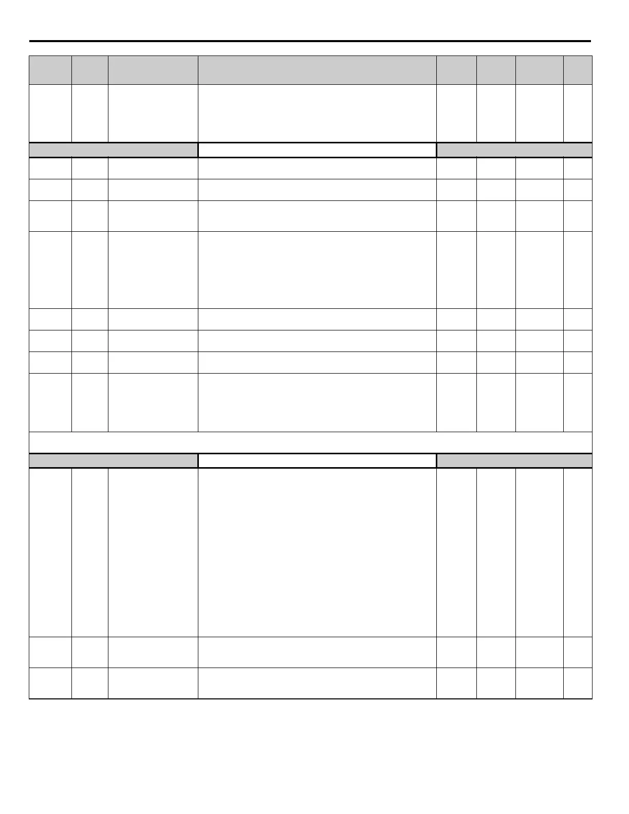
Parameter
No.
Modbus
Address
Parameter Name
Digital Operator
Display
Description
Setting
Range
Factory
Setting
Menu
Location
Page
No.

 Loading...


