C Standards Compliance
234 YASKAWA ELECTRIC TOEP C710616 38H YASKAWA AC Drive-L1000A Quick Start Guide
Low Voltage Wiring for Control Circuit Terminals
Wire low voltage wires with NEC Class 1 circuit conductors. Refer to national state or local codes for wiring. If external
power supply used, it shall be UL Listed Class 2 power source only or equivalent. Refer to NEC Article 725 Class 1,
Class 2, and Class 3 Remote-Control, Signaling, and Power Limited Circuits for requirements concerning class 1 circuit
conductors and class 2 power supplies.
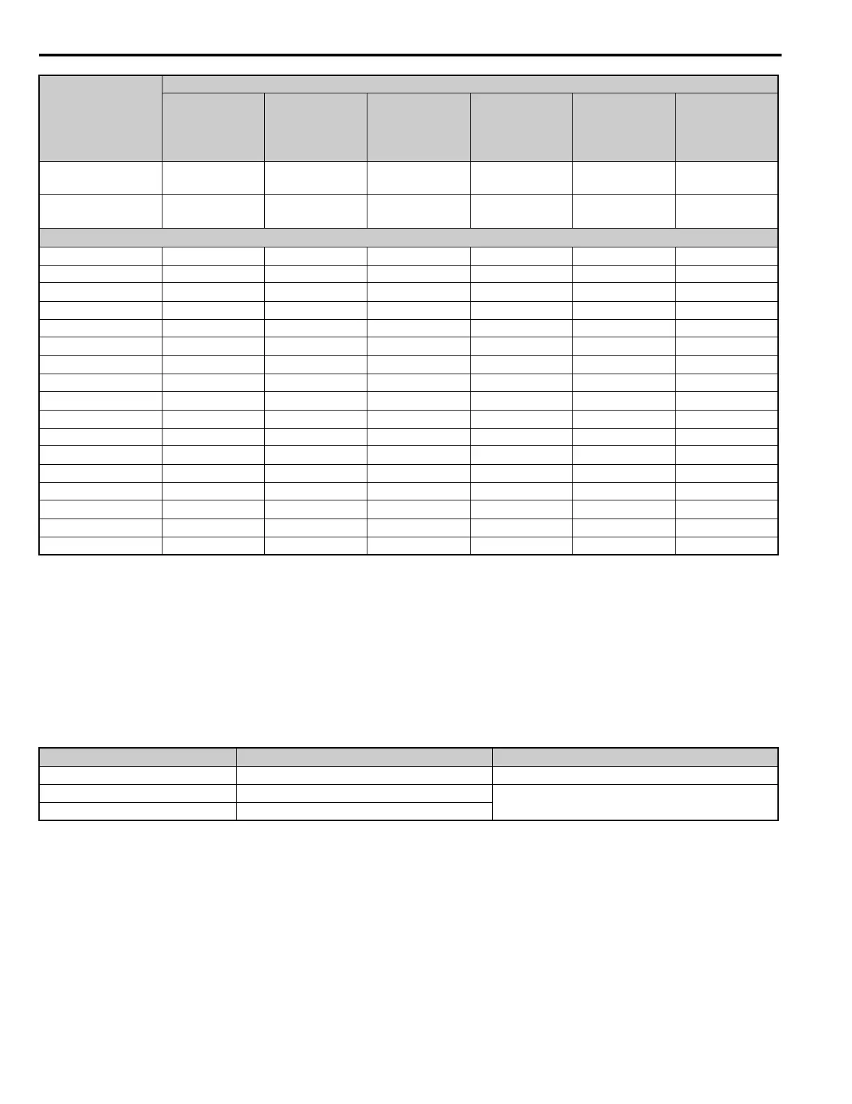
Table 67 Control Circuit Terminal Power Supply
Drive Short Circuit Rating
This drive is suitable for use on a circuit capable of delivering not more than 100,000 RMS symmetrical amperes,
600 Vac maximum (Up to 240 V in 200 V class drives, up to 480 V for 400 V class drives), when protected by Bussmann
Type FWH fuses as specified in Table 59 .
40450 350 410 700 700 1200 <4>
FWH-1000A
(1000)
40605 400 - 500 584 1000 1000 <4> 1600 <4>
FWH-1200A
(1200)
Three-Phase 600 V Class
50003 2 3.6 15 6.25 10 FWP-50B (50)
50004 3 5.1 15 8 15 FWP-60B (60)
50006 5 8.3 15 12 20 FWP-60B (60)
50010 7.5 12 20 20 35 FWP-70B (70)
50013 10 16 30 25 45 FWP-100B (100)
50017 15 23 40 40 60 FWP-100B (100)
50022 20 31 60 50 90 FWP-125A (125)
50027 25 38 75 60 100 FWP-125A (125)
50032 30 33 60 50 90 FWP-175A (175)
50041 40 44 75 75 125 FWP-175A (175)
50052 50 54 100 90 150 FWP-250A (250)
50062 60 66 125 110 175 FWP-250A (250)
50077 75 80 150 125 225 FWP-250A (250)
50099 100 108 175 175 300 FWP-350A (350)
50130 125 129 250 225 350 FWP-350A (350)
50172 150 158 300 250 400 FWP-600A (600)
50200 200 228 400 350 600 FWP-600A (600)
<1> Maximum MCCB Rating is 15 A, or 200% of drive input current rating, whichever is larger. MCCB voltage rating must be 600 Vac or greater.
<2> Maximum Time Delay fuse is 175% of drive input current rating. This covers any Class CC, J or T class fuse.
<3> Maximum Non-time Delay fuse is 300% of drive input current rating. This covers any CC, J or T class fuse.
<4> Class L fuse is also approved for this rating.
Input / Output Terminal Signal Power Supply Specifications
Open Collector Outputs P1, C1, P2, C2, DM+, DM- Requires class 2 power supply
Digital inputs S1-S8, SN, SC, SP, HC, H1, H2
Use the internal LVLC power supply of the drive. Use
class 2 for external power supply.
Analog inputs / outputs +V, -V, A1, A2, AC, AM, FM
Drive Model
CIMR-LU
L1000A in Heavy Duty Mode (C6-01 = 0)
Nominal
Output Power
HP
AC Drive Input
Amps
MCCB Rating
Amps <1>
Time Delay Fuse
Rating Amps <2>
Non-time Delay
Fuse Rating
Amps <3>
Bussmann
Semiconductor
Fuse Rating
(Fuse
Ampere) <4>
TOEP_C710616_38H_7_0.book 234 ページ 2015年11月11日 水曜日 午後7時40分