3 Electrical Installation
28 YASKAWA ELECTRIC TOEP C710616 38H YASKAWA AC Drive-L1000A Quick Start Guide
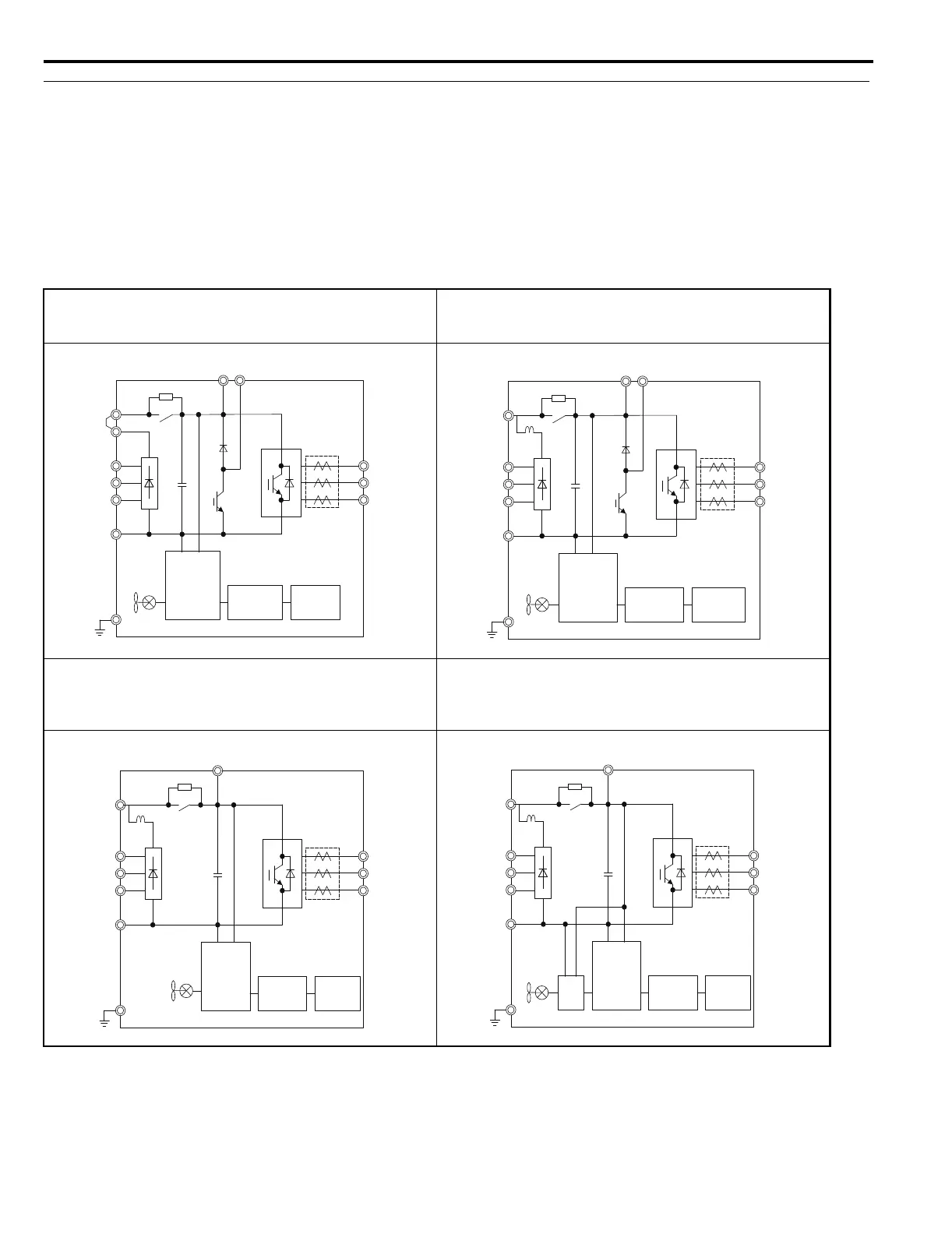
◆ Main Circuit Connection Diagram
Refer to the Figure 7 when wiring the main circuit of the drive. Connections may vary based on drive capacity. The DC
power supply for the main circuit also provides power to the control circuit.
NOTICE: Do not use the negative DC bus terminal “-” as a ground terminal. This terminal is at high DC voltage potential. Improper
wiring connections could damage the drive.
NOTICE: Equipment Hazard. Separate motor and/or braking circuit wiring (terminals, U/T1, V/T2, W/T3, +3, +2, +1,(-), B1, B2, from all
other wiring. Place motor wiring within its own conduit or cable tray with appropriate divider, and use shielded motor cable where
appropriate. Improper wiring practices could result in malfunction of drive due to electrical interference.
Figure 7 Drive main circuit configurations
CIMR-LU20008 to 20075
CIMR-LU40005 to 40039
CIMR-LU50003 to 50027
CIMR-LU20085, 20115
CIMR-LU40045, 40060
CIMR-LU50032, 50041
CIMR-LU20145 to 20180
CIMR-LU40075 to 40112
CIMR-LU50052 to 50077
CIMR-LU20215 to 20415
CIMR-LU40150 to 40605
CIMR-LU50003 to 50200
CIMR-LU50099 to 50200
+1
+2
–
R/L1
S/L2
T/L3
Relay
Gate board
Control
board
Operator
+
Current
sensor
U/T1
V/T2
W/T3
B1 B2
+1
–
R/L1
S/L2
T/L3
U/T1
V/T2
W/T3
B1 B2
DC link
choke
+
Relay
Gate board
Control
board
Operator
Current
sensor
+1
–
R/L1
S/L2
T/L3
U/T1
V/T2
W/T3
+
+3
DC link
choke
Relay
Gate board
Control
board
Operator
Current
sensor
+1
–
R/L1
S/L2
T/L3
U/T1
V/T2
W/T3
+3
+
24 V
Power
Supply
DC link
choke
Relay
Gate board
Control
board
Operator
Current
sensor
TOEP_C710616_38H_7_0.book 28 ページ 2015年11月11日 水曜日 午後7時40分