B Parameter Table
YASKAWA ELECTRIC TOEP C710616 38H YASKAWA AC Drive-L1000A Quick Start Guide 207
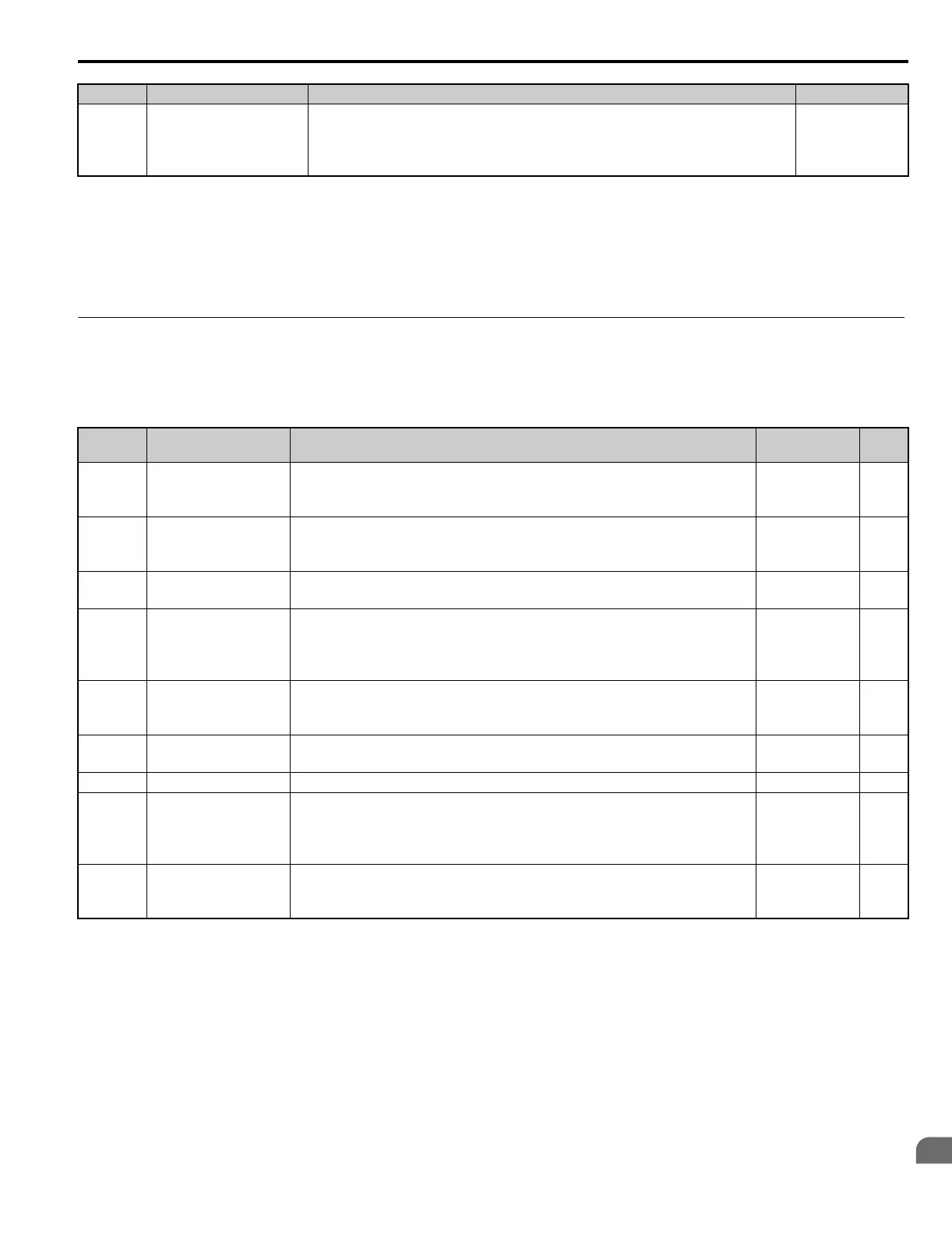
◆ U: Monitors
Monitor parameters allow the user to view drive status, fault information, and other data concerning drive operation.
■
U1: Operation Status Monitors
T2-19
<44>
Rotation Direction for
Auto-Tuning of PG-E3
Encoder Characteristics
Sets the direction of motor rotation for execution of Auto-Tuning of PG-E3 encoder
characteristics (T2-01 = 12).
0: Forward (Up)
1: Reverse (Down)
Default: 0
Min: 0
Max: 1
<4> Default setting value varies by the drive model (o2-04).
<9> Values shown here are for 200 V class drives. Double the value when using a 400 V class drive. Multiply value by 2.875 for 600 V class drives.
<10> The display resolution depends on the rated output power of the drive. Models CIMR-LU20008 to 20033, 40005 to 40018, and
50003 to 50013 display values in 0.01 A units, while models CIMR-LU20047 to 20415, 40024 to 40605, and 50017 to 50200
display values in 0.1 A units.
<30> Setting units are determined by the induced voltage constant unit selection for PM motors set to T2-13.
<43> When PG-E3 option connected: Max setting = 48
<44> Available in drive software versions PRG: 7017 or later.
No. Name Description
Analog Output
Level
Unit
U1-01 Speed Reference Monitors the speed reference.
10 V: Max
frequency
(-10 to +10 V)
0.01%
<29>
U1-02 Output Speed Displays the output speed.
10 V: Max
frequency
(-10 to +10 V)
0.01%
<29>
U1-03 Output Current Displays the output current.
10 V: Drive
rated current
<10> <40>
U1-04 Control Method
0: V/f Control
2: Open Loop Vector Control
3: Closed Loop Vector Control
7: Closed Loop Vector Control for PM
No signal output
available
–
U1-05 Speed Feedback Displays the motor speed feedback.
10 V: Max
Frequency
(-10 to +10 V)
0.01%
<29>
U1-06
Output Voltage
Reference
Displays the output voltage.
10 V: 200
Vrms
<9>
0.1 Vac
U1-07 DC Bus Voltage Displays the DC bus voltage. 10 V: 400 V
<9> 1 Vdc
U1-08 Output Power Displays the output power (this value is calculated internally).
10 V: Drive
rated power
(kW)
(-10 to +10 V)
<12>
U1-09 Torque Reference Monitors the internal torque reference.
10 V: Motor
rated torque
(-10 to +10 V)
0.1%
No. Name Description Setting
TOEP_C710616_38H_7_0.book 207 ページ 2015年11月11日 水曜日 午後7時40分

 Loading...


