3 Electrical Installation
34 YASKAWA ELECTRIC TOEP C710616 38H YASKAWA AC Drive-L1000A Quick Start Guide
◆ Main Circuit Wiring
This section describes the functions, specifications, and procedures required to safely and properly wire the main circuit
in the drive.
NOTICE: Only connect recommended devices to the drives braking transistor terminals. Failure to comply could result in damage to
the drive or braking circuit. Carefully review instruction manual TOBP C720600 0
when connecting a braking option to the drive.
NOTICE: Do not use the negative DC bus terminal “-” as a ground terminal. This terminal is at high DC voltage potential.
Improper wiring connections could damage the drive.
NOTICE: Equipment Hazard. Separate motor and/or braking circuit wiring (terminals, U/T1, V/T2, W/T3, +3, +2, +1,(-), B1, B2, from all
other wiring. Place motor wiring within its own conduit or cable tray with appropriate divider, and use shielded motor cable where
appropriate. Improper wiring practices could result in malfunction of drive due to electrical interference.
NOTICE: Equipment Hazard. Comply with proper wiring practices. The motor may run in reverse if the phase order is backward,
causing incorrect elevator direction movement. Connect motor input terminals U, V and W to drive output terminals U/T1,V/T2, and W/
T3. The phase order for the drive and motor should match.
NOTICE: Do not solder the ends of wire connections to the drive. Soldered wiring connections can loosen over time. Improper wiring
practices could result in drive malfunction due to loose terminal connections.
NOTICE: Do not switch the drive input to start or stop the motor. Frequently switching the drive on and off shortens the life of the DC
bus charge circuit and the DC bus capacitors, and can cause premature drive failures. For the full performance life, refrain from
switching the drive on and off more than once every 30 minutes.
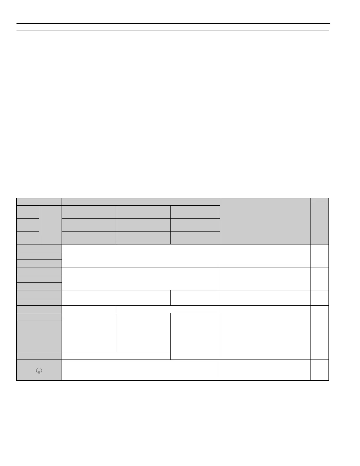
■ Main Circuit Terminal Functions
Table 9 Main Circuit Terminal Functions
Note: Use terminal B1 and - terminals when installing the braking unit (CDBR type) to the drives with built-in braking transistor
(20008 to 20115, 40005 to 40060, and 50003 to 50041).
Terminal Type
Function Page
200 V
Class
Model
CIMR-L
U
20008 to 20075 20085, 20115 20145 to 20415
400 V
Class
40005 to 40039 40045, 40060 40075 to 40605
600 V
Class
50003 to 50027 50032, 50041 50052 to 50200
R/L1
Main circuit power supply input Connects line power to the drive 26
S/L2
T/L3
U/T1
Drive output Connects to the motor 26
V/T2
W/T3
B1
Braking resistor Not available
Available for connecting a braking
resistor or a braking resistor unit option –
B2
+2 • DC reactor connection
(+1, +2) (remove the
shorting bar between
+1 and +2)
• DC power supply
input
(+1, –)
Not available
For connection
• of the drive to a DC power supply
(terminals +1 and – are not UL
approved)
• of dynamic braking options
–
+1
DC power supply input
(+1, –)
• DC power supply
input (+1, –)
• Braking unit
connection (+3, –)
–
+3 Not available
For 200 V class: 100 Ω or less
For 400 V class: 10 Ω or less
For 600 V class: 10 Ω or less
Grounding terminal 45
TOEP_C710616_38H_7_0.book 34 ページ 2015年11月11日 水曜日 午後7時40分