3 Electrical Installation
26 YASKAWA ELECTRIC TOEP C710616 38H YASKAWA AC Drive-L1000A Quick Start Guide
Figure 7
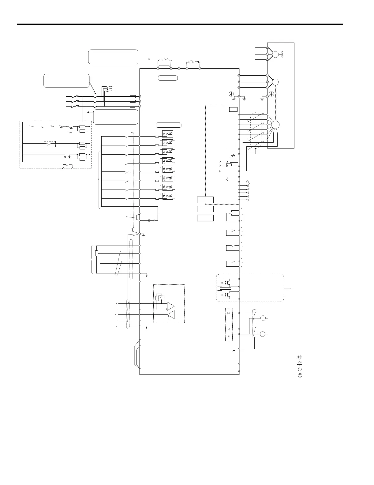
Figure 6 Drive Standard Connection Diagram (example: CIMR-LU20033)
<1> Remove the jumper when installing a DC link choke. Models CIMR-LU20085 through 20415, 40045
through 40605, and 50032 through 50200 come with a built-in DC link choke.
<2> Set L8-55 to 0 to disable the protection function of the built-in braking transistor of the drive when using an
optional regenerative converter or dynamic braking option.
<3> Set up a thermal relay sequence to disconnect drive main power in the event of an overheat condition on the
dynamic braking option.
<4> Self-cooling motors do not require the same wiring necessary for motors with separate cooling fans.
Shield ground terminal
+
−
+
−
DM
DM
H
1
H2
HC
<10>
R/L1
S/L2
T/L3
Fuse
MC
2MCCB
MB
ON
OFF
THRX
SA
1
2
TRX
MC
MA
TRX
Fault relay
contact
Braking resistor unit
Thermal relay trip contact
MC
MC
SA
SA
THRX
ELCB (MCCB)
R
T
S
Three-phase
power supply
200 to 240 V
50/60 Hz
<14>
2MCCB
r1
s1
t1
MC
Wiring sequence should shut off
power to the drive when a fault
output is triggered.
If running from a 400 V power
supply or 600 V power supply, a
step-down transformer is needed
to reduce the voltage to 200 V.
P1
P2
C1
C2
Photo Coupler 1
(During Frequency Output)
Photo Coupler 2
(not used)
Digital output
5 to 48 Vdc
2 to 50 mA
(default setting)
+
+
++
Terminals -, +1, +2, B1, B2 are
for connecting options. Never
connect power supply lines to
these terminals
DC link choke
(option)
UX
Thermal relay
(option)
+
+
++
+
−
UX
S
1
S2
S3
S4
S5
S6
S7
A1
A2
0
V
AC
R
R
S
S
IG
Drive
B112
B2
2
kΩ
S8
SC
0 V
FM
AM
AC
E (G)
<1>
<8>
<8>
<9>
<2><3>
−
+24 V
+V
MA
M
1
M2
MB
MC
Jumper
Braking resistor
(option)
Up command / Stop
External Fault
Fault Reset
Multi-step Speed 1
Not Used
Multi-function
digtial inputs
(default setting)
Sink / Source mode
selection wire jumper
(default: Sink)
Multi-function
analog inputs
Power supply +10.5 Vdc, max. 20 mA
Analog Input 1 (Speed Bias)
-10 to +10 Vdc (20 k
Ω
)
Analog Input 2 (Not used)
-10 to +10 Vdc (20 k
Ω
)
−V
Power supply, -10.5 Vdc, max. 20 mA
MEMOBUS/Modbus
comm. RS485/422
max. 115.2 kBps
Termination resistor
(120
Ω
, 1/2 W)
DIP
Switch S2
Fault relay output
250 Vac, max. 1 A
30 Vdc, max 1 A
(min. 5 Vdc, 10 mA)
Multi-function relay output (Brake Release Command)
250 Vac, max. 1 A
30 Vdc, max 1 A
(min. 5 Vdc, 10 mA)
Multi-function analog output 1
(Output Speed)
-10 to +10 Vdc (2mA)
Multi-function analog output 2
(Output Current)
-10 to +10 Vdc (2mA)
Main Circuit
Control Circuit
shielded line
twisted-pair shielded line
main circuit terminal
control circuit terminal
M3
M4
Multi-function relay output (Motor Contactor Close Command)
250 Vac, max. 1 A
30 Vdc, max 1 A
(min. 5 Vdc, 10 mA)
M5
M6
Multi-function relay output (Drive Ready)
250 Vac, max. 1 A
30 Vdc, max 1 A
(min. 5 Vdc, 10 mA)
SP
SN
FM
+
−
AM
<7>
Down command / Stop
Multi-step Speed 2
Multi-step Speed 3
FE
SD
NC
a+
a-
b-
z-
b+
z+
IP
IG
IP12
IP5
IG
SG
TB2
A pulse monitor signal
B pulse monitor signal
Z pulse monitor signal
CN3
PG
<4>
<2>
A+
A
B
Z
B+
Z+
TB1
PGX3
CN5-C
CN5-B
CN5-A
Option card
connector
M
U/T
1
V/T2
W/T
U/T1
V/T2
W/T3
3
Ground
Cooling fan
<6>
<5>
M
r1
s1
t1
FU
FV
FW
<12>
<13> <14>
<15>
EDM (Safety Electronic Device Monitor)
Safe Disable inputs
<11>
TOEP_C710616_38H_7_0.book 26 ページ 2015年11月11日 水曜日 午後7時40分