3 Electrical Installation
YASK AWA TOEPYAIL1E01A YASKAWA AC Drive L1000E Quick Start Guide 47
Wire the control circuit only after terminals have been properly grounded and main circuit wiring is complete. Refer to
Figure 27 for details. Prepare the ends of the control circuit wiring as shown in Figure 28. Refer to Wire Size and Torque
Specifications on page 45.
WARNING! Do not tighten screws beyond the specified tightening torque. Failure to comply may result in erroneous operation, damage
the terminal block, or cause injury due to fire from overheating of loose electrical connections.
NOTICE: Use shielded twisted-pair cables as indicated to prevent operating faults. Improper wiring practices could result in drive or
equipment malfunction due to electrical interference.
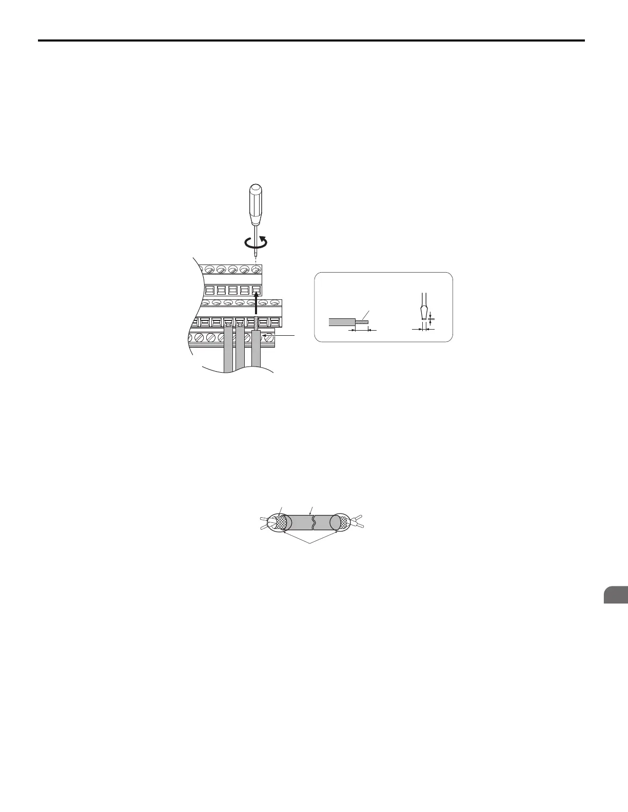
Connect control wires as shown in Figure 27.
Figure 27
Figure 27 Terminal Board Wiring Guide
When connecting control wires to the terminals, use shielded twisted-pair wires (treating wire ends as shown in Figure 28
and connect the shield to the ground terminal (E [G]) of the drive.
Figure 28
Figure 28 Preparing the Ends of Shielded Cables
NOTICE: Do not exceed 50 meters (164 ft.) for the control line between the drive and the operator when using an analog signal from a
remote source to supply the frequency reference. Failure to comply could result in poor system performance.
A – Loosen screw to insert wire C – Avoid fraying wire strands when stripping
insulation from wire. Strip length 5.5 mm (0.22 in.)
B – Single wire or stranded wire D – Blade depth of 0.4 mm (0.02 in.) or less
Blade width of 2.5 mm (0.10 in.) or less
A – Drive side D – Shield sheath (insulate with tape or heat-shrink tubing)
B – Insulation E – Shield
C – Control device side
A
B
C
D
Preparing wire
terminal ends
E
B
C
D