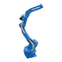
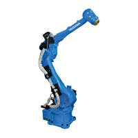
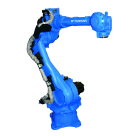
Allowable load for wrist axis and wrist flange
7 - 45
Fig. 7-3: Installing peripheral equipment mounts
4 threaded holes M8 x 14 4 threaded holes M12 x 24
2 threaded holes M5 x 9 4 threaded holes M20 x 39
2 threaded holes M6 x 11 4 threaded holes M6 x 11
A1, A2 and
A3
Wiring and valve
load
30 kg maximum.
Not more than 49 Nm for increasing the torque of
the upper arm
B Other max. 250 kg
A1
1
A3
A3
1
2
A3
A1
A1
3
A2
1
B
4
B
B
5
5
6
1
4
2
5
3
6
 Loading...
