5.2 Part Names and Working Axes
5-2
HW0482143
5.2 Part Names and Working Axes
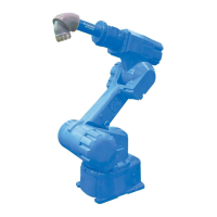
Fig. 8 Part Names and Working Axes
5.3 Manipulator Base Dimensions
Fig. 9 Manipulator Base Dimensions
Wrist
T+
T-
B+
B-
R-
R+
Wrist flange
Upper arm
(U-arm)
S+
L-
(S-head)
Rotary head
S-
Base
Lower arm
(L-arm)
L+
U-
U+
A
40
Units: mm
View A
Fitting surface
Fitting surfa
22 dia. (8 holes)
(For fixing the manipulator)
20 dia. (2 holes)
(Pin hole for manipula
positioning)
+0.021
0
16 dia. (2 holes)
(Pin hole for manipulat
positioning)
+0.018
0
350 0.1
290
0.1
290
0.1
640
290 0.1
893
290 0.1
540
290 0.1290 0.1
540
640
735
353 0.1
 Loading...