EasyManua.ls Logo

YASKAWA MP2000 Series User Manual

YASKAWA MP2000 Series
557 pages
To Next Page IconTo Next Page
To Previous Page IconTo Previous Page
Page #177 background imageLoading...
Page #177 background image
6.2 Motion Command Details
6.2.2 Latch Target Positioning (EX_POSING) (External Positioning)
6-12
5.
Set OW08 to 0 to execute the NOP motion command to complete the external positioning opera-
tion.
( 2 ) Holding
Axis travel can be stopped during command execution and then the remaining travel can be restarted. A command is
held by setting the Holds a Command bit (OW09, bit 0) to 1.
Set the Holds a Command bit (OW09, bit 0) to 1. The axis will decelerate to a stop.
When the axis has stopped, the Command Hold Completed bit (IW09, bit 1) will turn ON.
Reset the Holds a Command bit (OW09, bit 0) to 0.
The command hold status will be cleared and the remaining portion of the positioning will be restarted.
( 3 ) Aborting
Axis travel can be stopped during command execution and the remaining travel canceled by aborting execution of a
command. A command is aborted by setting the Interrupt a Command bit (OW09, bit 1) to 1.
Set the Interrupt a Command bit (OW09, bit 1) to 1. The axis will decelerate to a stop.
When the axis has stopped, the remain travel will be canceled and the Positioning Completed bit (IW0C,
bit 1) will turn ON.
This type of operation will also be performed if the motion command is changed during axis movement.
( 4 ) Related Parameters
[ a ] Setting Parameters
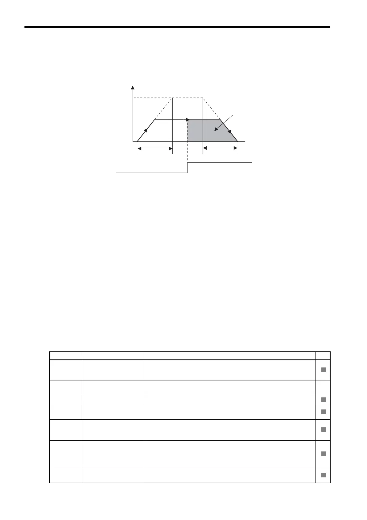
Speed
(%)
(100%)
0
Time (t)
Straight line deceleration time constant
Rated speed
Latch signal
(external positioning signal)
Positioning
speed
External positioning
final travel distance
Straight line acceleration time constant
EX_POSING Operating Pattern
Parameter Name Setting SVR
OW00
Bit 0
Servo ON
Turn the power to the Servomotor ON and OFF.
1: Power ON to Servomotor, 0: Power OFF to Servomotor
Turn ON the power before setting the Motion Command (OW08) to 2.
OW01
Bit 3
Speed Loop
P/PI Switch
Switch the speed control loop between PI control and P control.
0: PI control, 1: P control
OW03 Function Setting 1
Set the speed unit, acceleration/deceleration units, and filter type.
OW04 Function Setting 2
Set the external positioning signal.
2: phase-C pulse, 3: /EXT1, 4: /EXT2, 5: /EXT3
OW08 Motion Command
The positioning starts when this parameter is set to 2.
The operation will be canceled if this parameter is set to 0 during EX_POSING
command execution.
OW09
Bit 0
Holds a Command
The axis will decelerate to a stop if this bit is set to 1 during execution of
EX_POSING command execution.
The positioning will restart if this bit is reset to 0 when a command is being
held.
OW09
Bit 1
Interrupt a Command
The axis will decelerate to a stop if this bit is set to 1 during EX_POSING com-
mand execution.
R
R
R
R
R
R

Table of Contents

Other manuals for YASKAWA MP2000 Series

Question and Answer IconNeed help?

Do you have a question about the YASKAWA MP2000 Series and is the answer not in the manual?

YASKAWA MP2000 Series Specifications

General IconGeneral
Control MethodDigital Control
Communication ProtocolsPROFIBUS-DP, MECHATROLINK-II
Programming LanguageStructured Text
Operating Temperature0°C to 55°C
Storage Temperature-20°C to 65°C

Summary

Overview

SVB Module Overview and Features

Provides an overview and features of the SVB Module, including its capabilities and architecture.

Specifications

Details the hardware and general specifications of the SVB-01 Module.

Settings and Installation

LED Indicators and Switch Settings

Explains LED indicators, status indications, and switch settings for the SVB-01 Module.

Self-configuration and Created Definition Files

Self-configuration Overview

Explains the self-configuration function and how it reduces system startup time.

How to Execute Self-configuration

Describes two methods for executing self-configuration: using DIP switch and using MPE720.

System Startup Using Self-Configuration

Details system startup procedures for first-time setup, adding devices, and replacing devices.

Motion Parameters

Motion Parameter Setting Examples

Motion Commands

Motion Command Details

Provides detailed descriptions of individual motion commands, including their execution procedures and parameters.

Absolute Position Detection

Absolute Position Detection Function

Explains the function of absolute position detection and its features.

Setting Procedure of Absolute Position Detection Function

Details the system startup flowchart and initialization procedures for absolute encoders.

Absolute Position Detection for Finite Length Axes

Describes parameter settings and precautions for finite length axes using absolute position detection.

Absolute Position Detection for Infinite Length Axes

Explains position control methods for infinite length axes using absolute position detection.

Settings for Connecting Inverters

Operating Inverters Using an MPE720

Guides on checking items before operation, operation precautions, and procedures for using inverters with MPE720.

Inverter Alarm and Warning Codes

Classifies and lists inverter errors, alarms, and warnings.

Utility Functions

Overtravel Function

Details connections and parameter settings for stopping the machine when the moving part exceeds movement range.

Software Limit Function

Explains setting upper and lower limits for machine movement to prevent runaway or damage.

Troubleshooting

Troubleshooting System Errors

Provides information for troubleshooting system errors, including register allocations and error status.

Motion Program Alarms

Details motion program alarms, their configuration, and alarm codes.

List of Causes for Command Error Occurrence

Lists causes of command error occurrences for each motion command.

Troubleshooting Motion Errors

Explains details and corrective actions for errors occurring in motion control functions.

Related product manuals