6.2 Motion Command Details
6.2.2 Latch Target Positioning (EX_POSING) (External Positioning)
6-11
6.2.2 Latch Target Positioning (EX_POSING) (External Positioning)
The EX_POSING command positions the axis to the target position using the specified target position and speed.
Parameters related to acceleration and deceleration are set in advance.
If the external positioning signal turns ON during axis movement, the axis will move the distance specified for the
External Positioning Final Travel Distance from the point at which the external positioning signal turned ON, and then
stop. If the external positioning signal does not turn ON, positioning will be completed to the original target position.
When using an SGDV or SGD7S SERVOPACK, the torque limit can be set and changed during SERVOPACK opera-
tion. For details, refer to Setting and Changing Torque Limit during SGDV or SGD7S SERVOPACK Operations of
4.4.2 ( 12 ). Also, refer to Precautions of 6.2.1 ( 3 ).
When using a DC Power Input Σ-V Series SERVOPACK (Model: SGDV-E1), refer to 11.7.4 Motion Com-
mand Operation for External Latches with DC Power Input
Σ
-V-series SERVOPACKs.
For more information on the maximum allowable value for acceleration and deceleration, refer to Changing the max-
imum value of acceleration and deceleration for SGDV or SGD7S SERVOPACKs of 4.4.2 ( 23 ).
( 1 ) Executing/Operating Procedure
1.
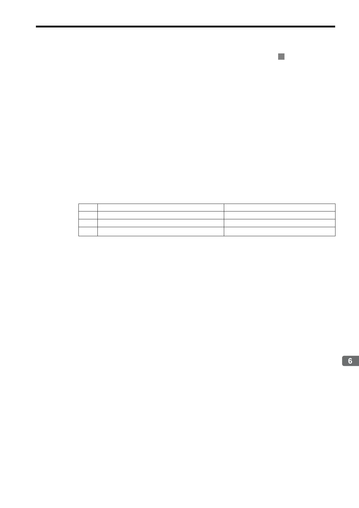
Check to see if all the following conditions are satisfied.
* This condition is a basic execution condition. Refer to Chapter 7 Switching Commands during Execution when
changing the command that is being executed to an EX_POSING command.
2.
Set the following motion setting parameters.
External Positioning Final Travel Distance: OL46
External Positioning Signal Setting: OW04
Speed Reference Setting: OL10
Filter Type Selection: OW03, bits 8 to B
Speed Loop P/PI Switch: OW01
Position Reference Setting: OL1C
The Speed Reference
Setting
can be changed during operation.
An override of between 0% to 327.67% can be set for the speed reference.
A latch zone can be set as long as it is supported by the SERVOPACK being used.
3.
Set OW08 to 2 to execute the EX_POSING motion command to use the preceding settings in the
same scan.
4.
Turn ON the external positioning signal.
The axis will be moved the External Positioning Final Travel Move Distance and decelerate to a stop.
IW09, bit 8 will turn ON when the axis stops and external positioning has been completed.
No. Execution Conditions Confirmation Method
1 There are no alarms. Both IL02 and IL04 are 0.
2 The Servo ON condition. IW00, bit 1 is ON.
3
Motion command execution has been completed.
*
IW08 is 0 and IW09, bit 0 is OFF.