10.3 Main Commands and Subcommands
10.3.3 Command Details
10-17
Settings for Connecting Inverters
Monitoring Parameters
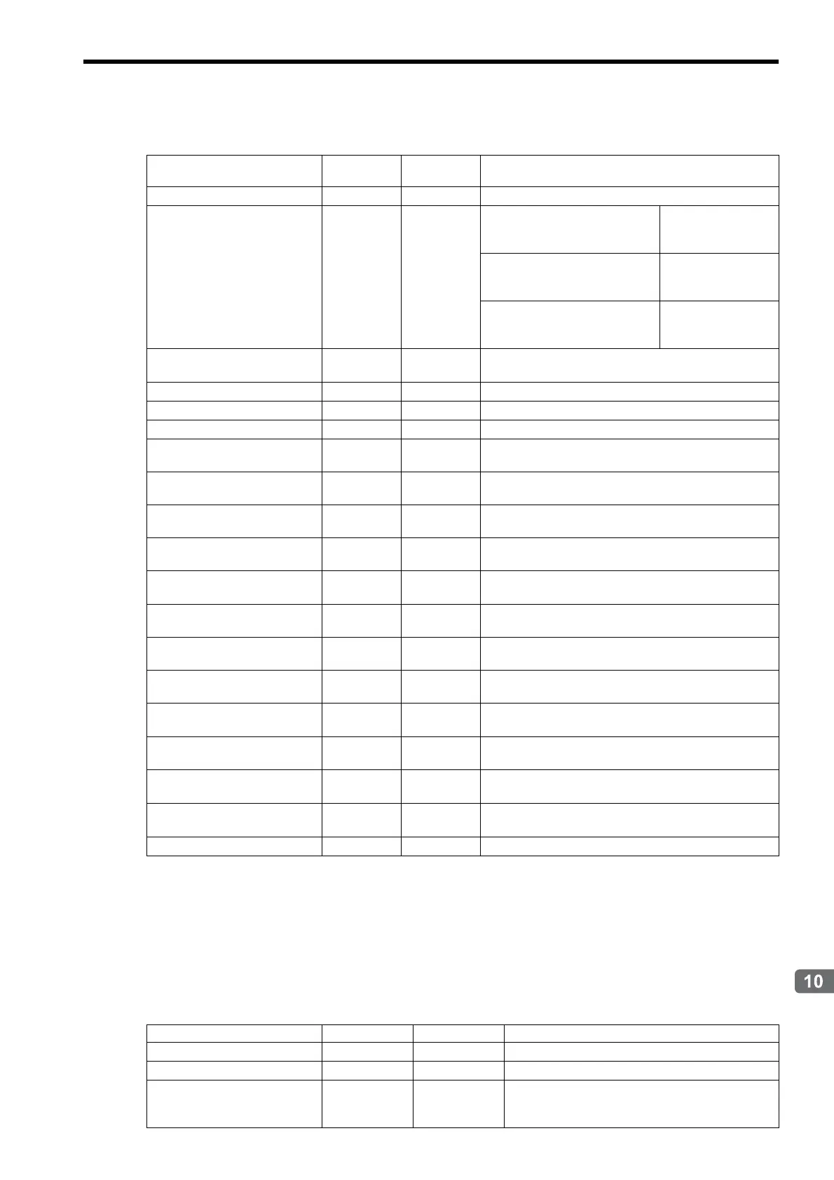
( 3 ) Read User Constant
Description
Reads the specified user constant from the Inverter.
Valid only when using MECHATROLINK-II 17-byte mode or MECHATROLINK-I.
Use a subcommand when using MECHATROLINK-II 32-byte mode.
Setting Parameters
Name Register No.
Setting
Range
Remarks
Command Response Code
IW08 0 to 8 01: Inverter Drive Control
Command Status
IW09 Bit
Bit 0 (Command execution flag)
ON while the com-
mand is being exe-
cuted
Bit 3 (Command error completed
status)
ON when an error
occurs during com-
mand processing
Bit 8 (Command execution com-
pleted)
ON when command
execution is com-
pleted.
Input Data Option Selection
Monitor
IW0D Bit Displays optional input data.
Status
IW10 Bit Inverter status
Output Frequency
IW11
Output Current
IW12
Motor Speed (Option)
IW13
Valid when Input Data Option Selection (OW0D) bit 0
is ON.
Torque Reference
IW14
Valid when Input Data Option Selection (OW0D) bit 1
is ON.
Encoder Counter (Option)
IW15 0 to 65535
Valid when Input Data Option Selection (OW0D) bit 2
is ON.
Frequency Reference
IW16
Valid when Input Data Option Selection (OW0D) bit 3
is ON.
Multi-function Analog Input
A2 (Option)
IW17
Valid when Input Data Option Selection (OW0D) bit 4
is ON.
Main Bus Voltage (Option)
IW18
Valid when Input Data Option Selection (OW0D) bit 5
is ON.
Alarm Code (Option)
IW19
Valid when Input Data Option Selection (OW0D) bit 6
is ON.
Alarm Code (Option)
IW1A
Valid when Input Data Option Selection (OW0D) bit 7
is ON.
Multi-function Analog Input
A3 (O
ption)
IW1C
Vali
d when Input Data Option Selection (OW0D) bit 9
is ON.
Digital Input Terminal (Option)
IW1D
Valid when Input Data Option Selection (OW0D) bit A
is ON.
Multi-function Analog Input
A1 (Option)
IW1E
Valid when Input Data Option Selection (OW0D) bit B
is ON.
Encoder Counter (CH2) (Op-
tion)
IW1F
Valid when Input Data Option Selection (OW0D) bit C
is ON.
Response Alarm Code
IW30 0 to FFFF Inverter alarm code
Name Register No. Setting Range Remarks
Command Code
OW08 0 to 8 02: Read User Constant
Inverter User Constant Number
OW3C 0 to FFFFH
Inverter User Constant Number
Size
OW3D 1 to 4
Data type: Word (Enter the size of the user constant
read out from the leading user constant number of the
inverter.)