EasyManua.ls Logo

YASKAWA MP2000 Series User Manual

YASKAWA MP2000 Series
557 pages
To Next Page IconTo Next Page
To Previous Page IconTo Previous Page
Page #255 background imageLoading...
Page #255 background image
6.2 Motion Command Details
6.2.24 Phase References (PHASE)
6-90
4.
Execute another motion command to cancel the phase control mode.
( 2 ) Holding and Aborting
The Holds a Command bit (OW09, bit 0) and the Interrupt a Command bit (OW09, bit 1) cannot be used.
( 3 ) Related Parameters
[ a ] Setting Parameters
[ b ] Monitoring Parameters
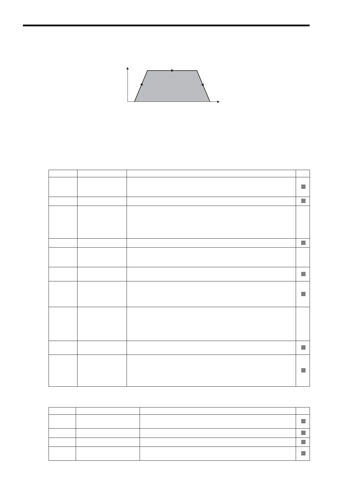
PHASE Operating Pattern
0
Speed (%)
Time (t)
Position
Parameter Name Setting SVR
OW00
Bit 0
Servo ON
Turns the power to the Servomotor ON and OFF.
1: Power ON to Servomotor, 0: Power OFF to Servomotor
Turn ON the power before setting the Motion Command (OW08) to 25.
OW03 Function Setting 1
Sets the speed unit, acceleration/deceleration units, and filter type.
OW05
Bit 1
Phase Reference
Creation Calcula-
tion Disable
Disables/enables phase reference generation processing when executing phase ref-
erence commands. This parameter enables setting processing appropriate to an elec-
tronic shaft or electronic cam.
Enable this processing when an electronic shaft is being used, and dis-
able it when an electronic cam is being used.
OW08 Motion Command
Phase control operation is started when this parameter is set to 25.
OW09
Bit 6
Phase
Compensation Type
If using a system with an electronic cam, select a setting method for the phase com-
pensation for the reference value of the cam pattern.
0: Incremental addition mode, 1: Absolute mode
OL10
Speed Reference
Setting
Set the speed reference. The setting can be changed during operation.
The unit depends on the Function Setting 1 setting (OW

03, bits 0 to 3).
OL16
Second Speed Com-
pensation
Set the speed feed forward amount for the Phase Reference command (PHASE).
The setting unit for Speed Compensation (setting parameter OW31) is 0.01%
(fixed). The unit for this parameter, however, can be selected by the user. When
used at the same time as OW31, speed compensation can be performed twice.
OL28
Phase
Correction Setting
Set the phase correction amount in reference units.
Set the number of pulses for phase compensation in pulses when an
electronic shaft is being used.
Use the incremental addition mode to calculate the cam pattern target
position when an electronic cam is being used.
OW31
Speed Compensa-
tion
Set the speed feed forward gain as a percentage of the rated speed.
The setting units for this parameter is 0.01% (fixed).
OW3A Filter Time Constant
Set the acceleration/deceleration filter time constant. Exponential acceleration/
deceleration or a moving average filter can be selected in the Function Setting 1
(OW03, bits 8 to B).
Change the setting only after pulse distribution has been completed for the com-
mand (IW0C, bit 0 is ON).
Parameter Name Monitor Contents SVR
IW00
Bit 1
Running (At Servo ON)
Indicates the Servo ON status.
1: Power supplied to Servomotor, 0: Power not supplied to Servomotor
IL02 Warning
Stores the most current warning.
IL04 Alarm
Stores the most current alarm.
IW08
Motion Command Re-
sponse Code
Indicates the motion command that is being executed.
The response code will be 25 during PHASE command execution.
R
R
R
R
R
R
R
R
R
R
R

Table of Contents

Other manuals for YASKAWA MP2000 Series

Question and Answer IconNeed help?

Do you have a question about the YASKAWA MP2000 Series and is the answer not in the manual?

YASKAWA MP2000 Series Specifications

General IconGeneral
Control MethodDigital Control
Communication ProtocolsPROFIBUS-DP, MECHATROLINK-II
Programming LanguageStructured Text
Operating Temperature0°C to 55°C
Storage Temperature-20°C to 65°C

Summary

Overview

SVB Module Overview and Features

Provides an overview and features of the SVB Module, including its capabilities and architecture.

Specifications

Details the hardware and general specifications of the SVB-01 Module.

Settings and Installation

LED Indicators and Switch Settings

Explains LED indicators, status indications, and switch settings for the SVB-01 Module.

Self-configuration and Created Definition Files

Self-configuration Overview

Explains the self-configuration function and how it reduces system startup time.

How to Execute Self-configuration

Describes two methods for executing self-configuration: using DIP switch and using MPE720.

System Startup Using Self-Configuration

Details system startup procedures for first-time setup, adding devices, and replacing devices.

Motion Parameters

Motion Parameter Setting Examples

Motion Commands

Motion Command Details

Provides detailed descriptions of individual motion commands, including their execution procedures and parameters.

Absolute Position Detection

Absolute Position Detection Function

Explains the function of absolute position detection and its features.

Setting Procedure of Absolute Position Detection Function

Details the system startup flowchart and initialization procedures for absolute encoders.

Absolute Position Detection for Finite Length Axes

Describes parameter settings and precautions for finite length axes using absolute position detection.

Absolute Position Detection for Infinite Length Axes

Explains position control methods for infinite length axes using absolute position detection.

Settings for Connecting Inverters

Operating Inverters Using an MPE720

Guides on checking items before operation, operation precautions, and procedures for using inverters with MPE720.

Inverter Alarm and Warning Codes

Classifies and lists inverter errors, alarms, and warnings.

Utility Functions

Overtravel Function

Details connections and parameter settings for stopping the machine when the moving part exceeds movement range.

Software Limit Function

Explains setting upper and lower limits for machine movement to prevent runaway or damage.

Troubleshooting

Troubleshooting System Errors

Provides information for troubleshooting system errors, including register allocations and error status.

Motion Program Alarms

Details motion program alarms, their configuration, and alarm codes.

List of Causes for Command Error Occurrence

Lists causes of command error occurrences for each motion command.

Troubleshooting Motion Errors

Explains details and corrective actions for errors occurring in motion control functions.

Related product manuals