10.4 Motion Parameter Details
10.4.3 Monitoring Parameter List
10-38
IL04
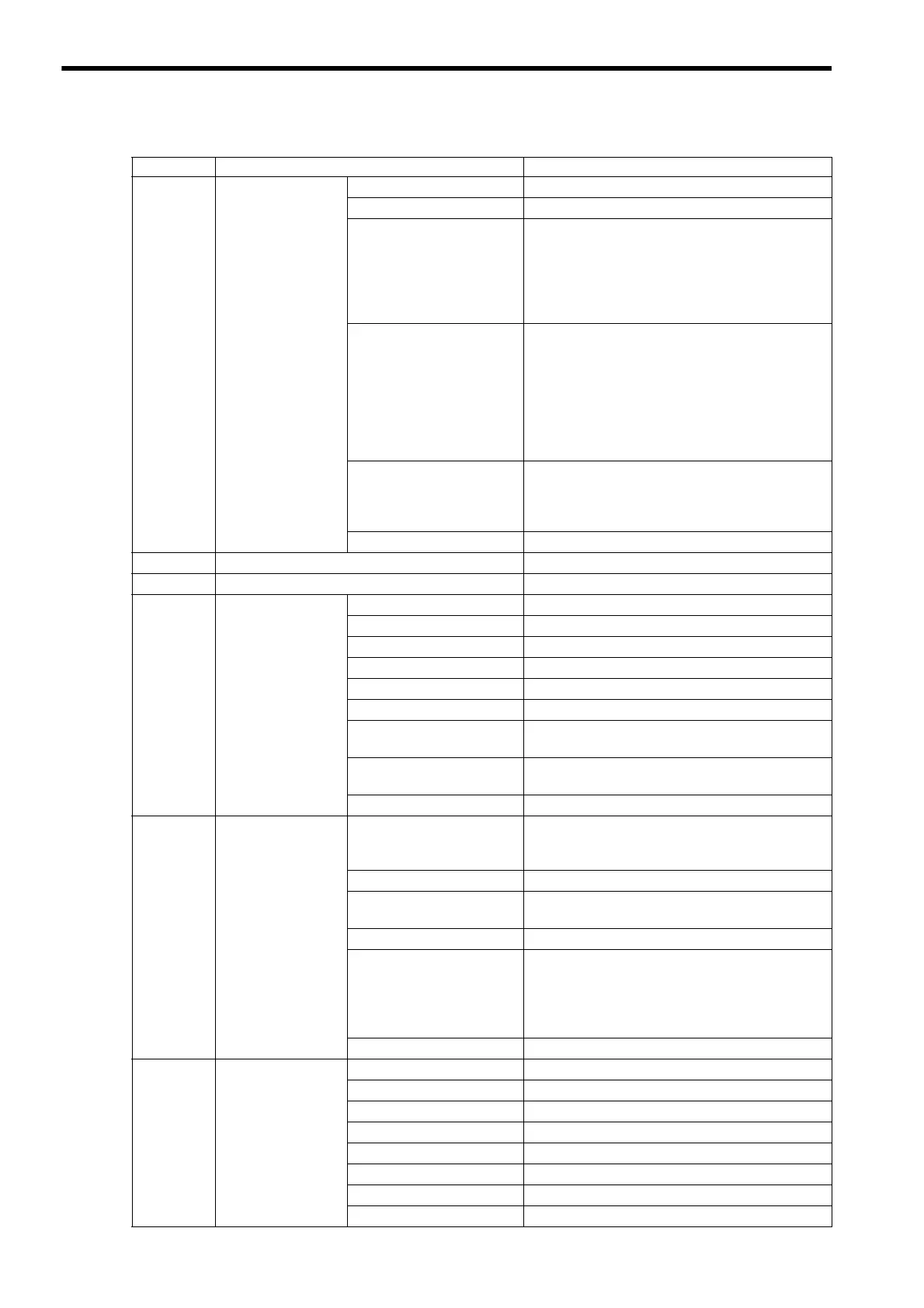
Alarm
Bits 0 to E
Reserved by the system
Bit F: User Constant Error
Not used
Bit 10: Synchronization
Communication Error
Turns ON when SVB Module watchdog timer timeout
error is detected.
Valid when the WDT Abnormality Detection Mask
bit of the fixed parameter Function Selection Flag 2 is
set to Disabled.
This alarm can be cleared by executing Alarm Clear.
Bit 11: Communication
Warning
Turns ON when communication error occurs.
Valid when:
Communication Abnormality Detection Mask bit of
the fixed parameter Function Selection Flag 2 is set to
Disabled, and Alarm is selected for Communication
Selection is Abnormal of the fixed parameter Func-
tion Selection Flag 3.
This alarm can be cleared by executing Alarm Clear.
Bit 12: Communication
Timeout Error
Turns ON when no response to the sent command or
subcommand has been returned from the Inverter for
five seconds.
This alarm can be cleared by executing Alarm Clear.
Bits 13 to 1F
Reserved by the system
IW06
−
Reserved by the system
IW07
−
Reserved by the system
IW08
Command
Response Code
00: No Command
No command is selected.
01: Inverter Drive Control
Control Inverter Drive is selected.
02: Read User Constant
Read User Constant is selected.
03: Write User Constant
Write User Constant is selected.
04: Alarm Monitor
Alarm Monitor is selected.
05: Alarm History Monitor
Alarm History Monitor is selected.
06: User Constant RAM
Writing
User Constant RAM Writing is selected.
07: User Constant
EEPROM Writing
User Constant EEPROM Writing is selected.
08: Transmission Reference
Transmission Reference is selected
IW09
Command Status
Bit 0: Command Execution
Flag
ON during command execution
Always ON when Transmission Reference command
is selected.
Bits 1and 2
Reserved by the system
Bit 3: Command Error
Completed Status
Turns ON when the command execution ends with an
error.
Bits 4 to 7
Reserved by the system
Bit 8: Command Execution
Completed
Turns ON when command execution is completed.
With a Inverter Drive Control command, data input
and output will continue after command execution is
completed.
Always ON when No Command is selected.
Bits 9 to F
Reserved by the system
IW0A
Subcommand
Response Code
00: No Command
N
o subcomm
and is selected.
01: Inverter I/O Control
Inverter I/O Control is selected.
02: Read User Constant
Read User Constant is selected.
03: Write User Constant
Write User Constant is selected.
04: Alarm Monitor
Alarm Monitor is selected.
05: Alarm History Monitor
Alarm History Monitor is selected.
08: Transmission Reference
Transmission Reference is selected.
09: Read Fixed Parameters
Read Fixed Parameters is selected.
(cont’d)
Register No. Name Contents
 Loading...


