10.4 Motion Parameter Details
10.4.5 Inverter Input Data Details
10-47
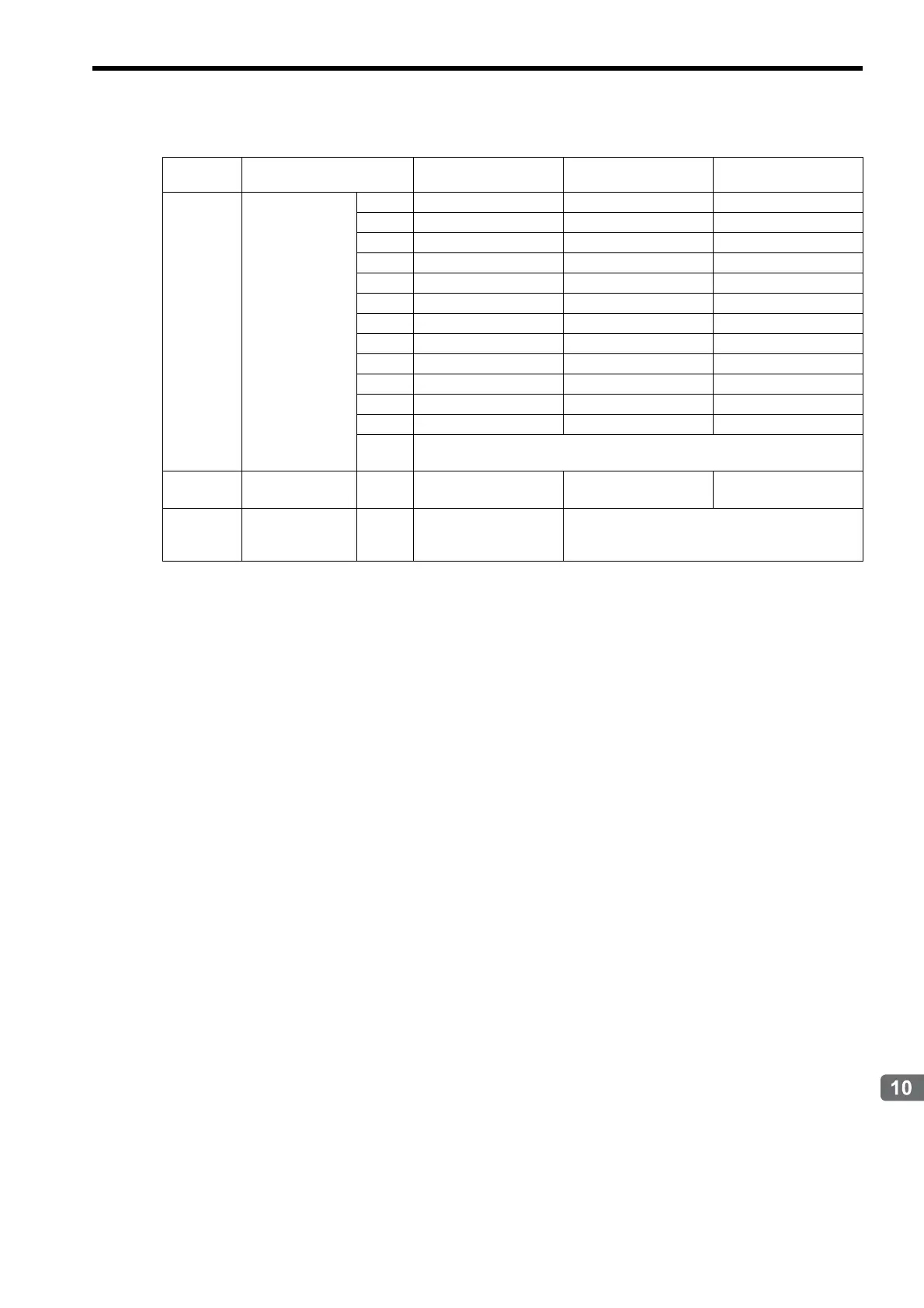
Settings for Connecting Inverters
IW1D
Digital Input
Terminal (Option)
Bit 0 Terminal 1 Status Terminal 1 Status Terminal 1 Status
Bit 1 Terminal 2 Status Terminal 2 Status Terminal 2 Status
Bit 2 Terminal 3 Status Terminal 3 Status Terminal 3 Status
Bit 3 Terminal 4 Status Terminal 4 Status Terminal 4 Status
Bit 4 Terminal 5 Status Terminal 5 Status Terminal 5 Status
Bit 5 Terminal 6 Status Terminal 6 Status Terminal 6 Status
Bit 6 Terminal 7 Status Terminal 7 Status Terminal 7 Status
Bit 7 Terminal 8 Status Terminal 8 Status Terminal 8 Status
Bit 8 Terminal 9 Status Terminal 9 Status Terminal 9 Status
Bit 9 Terminal 10 Status Terminal 10 Status Terminal 10 Status
Bit A Terminal 11 Status Terminal 11 Status Terminal 11 Status
Bit B Terminal 12 Status Terminal 12 Status Terminal 12 Status
Bits C
to F
Reserved by the system.
IW1E
Multi-function An-
alog Input A1
Unit: 0.1% Unit: 0.1% Unit: 0.1% (FR input)
IW1F
Encoder Counter
(ch2) (Option)
Unit: pulse
(Valid when a PG-Y2 is
connected.)
Reserved by the system.
(cont’d)
Register
No.
Name Varispeed G7 Varispeed F7 VSminiV7

 Loading...


