5 Installation Procedure
YASKAWA ELECTRIC SIEP C730600 70B V1000 Option SI-EP3/V Technical Manual 23
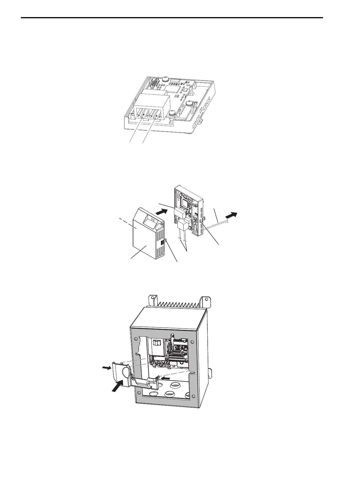
22. Connect the PROFINET Cat 5e communication cable to the option modular connector CN1 port 1 or port 2.
Install PROFINET communications cables apart from main-circuit wiring and other electrical and power lines.
Ensure the cable end is firmly connected (see Figure 32).Refer to Communication Cable Specifications on
page 26 for details of installing.
Note: Do not connect or disconnect the communication cable while the drive is powered up or while the drive is in operation. Failure to
comply may cause a static discharge, which will cause the option card to stop working properly. Cycle power on the drive and
option card to reestablish functionality.
Figure 25
Figure 25 Option Modular Connector CN1 Port 1 and Port 2 for Communication Cable
23. Use the second option modular connector CN1 port to daisy chain a series of drives where applicable.
24. For IP20/Open-Chassis or IP20/UL Type 1 enclosure models, go to Step 31. on page 25.
25. For IP66/UL Type 4X enclosure models, attach the option cover by aligning the tabs with the mounting holes and
seat the front cover into place (see Figure 26).
Figure 26
Figure 26 Attach the Option Cover
26. For IP66/UL Type 4X enclosure models, reattach the lower terminal cover, (on certain models), to the drive by
aligning the left and right tabs and snap into place (see Figure 27).
Figure 27
Figure 27 Reattach the IP66/UL Type 4X Lower Terminal Cover
Option cover
Mounting tab
Cover
mounting slot
Cover
mounting slot
Ground wire to
drive ground screw
Mounting tab
Cat5E cables
PROFINET_E_conditional.fm 23 ページ 2016年6月20日 月曜日 午後8時2分