Servodrives Dimensional Drawings
A
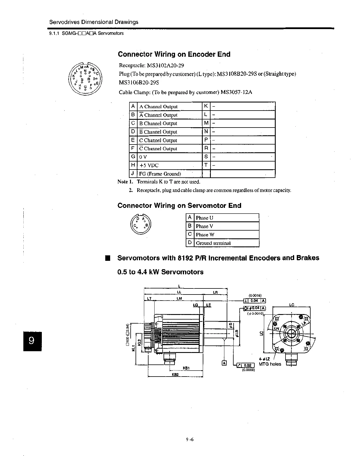
A Channel Output
K
-
B
A Channel Output
L —
C
B Channel Output
M —
D
B Channel Output
N —
E
C Channel Output
P
—
F
C Channel Output
R —
G
0 V
S —
H
+5 VDC
T
—
J
FG (Frame Ground)
A
Phase U
B
Phase V
C
Phase W
D
Ground terminal
9.1.1 SGMG-0111ADA Servomotors
Connector Wiring on Encoder End
Receptacle: MS3102A20-29
Plug (To be prepared by customer) (L type): MS3108B20-29S or (Straight type)
MS3106B20-295
Cable Clamp: (To be prepared by customer) MS3057-12A
Note 1. Terminals K to T are not used.
2. Receptacle, plug and cable clamp are common regardless of motor capacity.
Connector Wiring on Servomotor End
■ Servomotors with 8192 P/R Incremental Encoders and Brakes
0.5 to 4.4 kW Servomotors
L
ri
LT
LL
LM
LR
(0.0016)
47-
LG
LE
KB1
KB2
.11 0.04 A
#0.04
A
(p 0.0016
—V
0.02
(0.0008)
4- ot LZ
MTG holes
LC
9 -6
 Loading...


