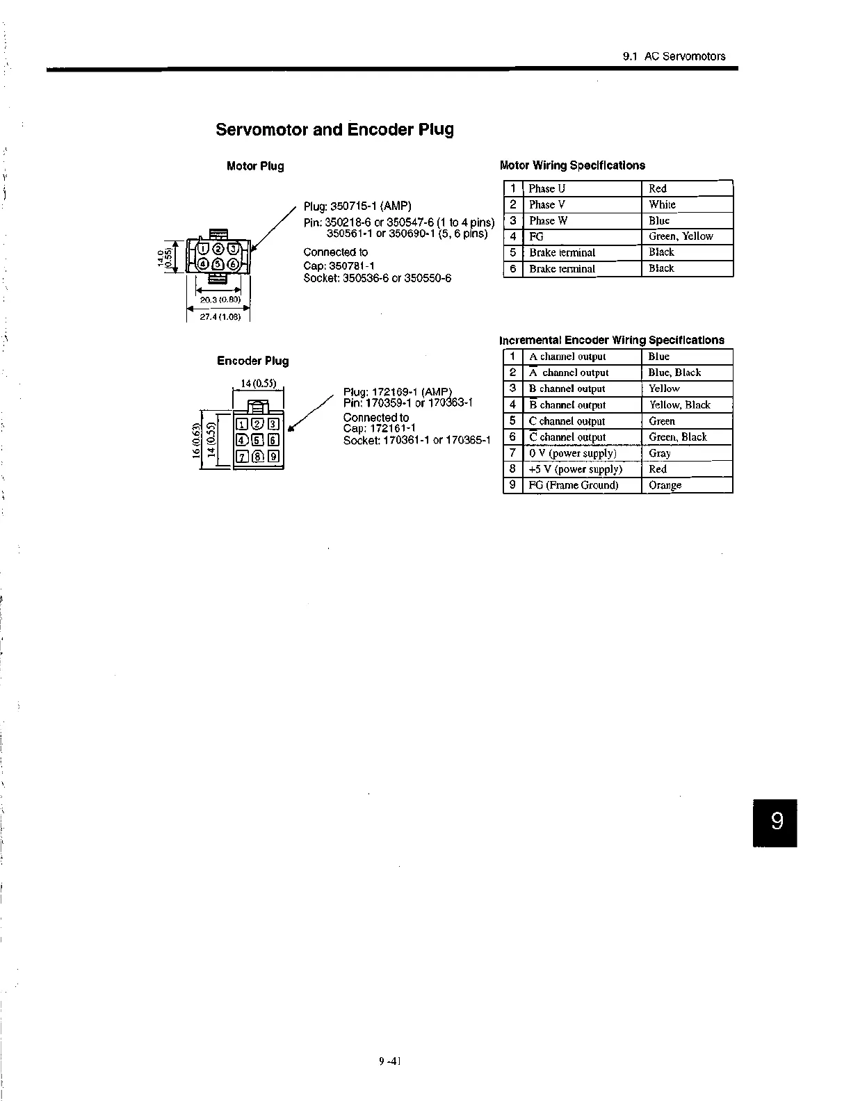
EasyManuals Logo

YASKAWA SGDB Series User Manual

YASKAWA SGDB Series
284 pages
To Next Page IconTo Next Page
To Previous Page IconTo Previous Page
Page #200 background imageLoading...
Page #200 background image
9.1 AC Servomotors
1 Phase U Red
2 Phase V White
3 Phase W Blue
4 FG Green, Yellow
5 Brake terminal Black
6 Brake terminal Black
1
A channel output
Blue
2 A channel output Blue, Black
3 B channel output Yellow
4
B channel output Yellow, Black
5 C channel output Green
6 C channel output Green, Black
7 0 V (power supply)
Gray
8 +5 V (power supply)
Red
9 FG (Frame Ground)
Orange
Servomotor and Encoder Plug
Motor Plug
Encoder Plug
14 (0.55)
'10
1
fffl
Plug: 350715-1 (AMP)
Pin: 350218-6 or 350547-6 (1 to 4 pins)
350561-1 or 350690-1 (5, 6 pins)
Connected to
Cap: 350781-1
Socket: 350536-6 or 350550-6
Plug: 172169-1 (AMP)
Pin: 170359-1 or 170363-1
Connected to
Cap: 172161-1
Socket: 170361-1 or 170365-1
Motor Wiring Specifications
Incremental Encoder Wiring Specifications
9

Table of Contents

Questions and Answers:

Question and Answer IconNeed help?

Do you have a question about the YASKAWA SGDB Series and is the answer not in the manual?

YASKAWA SGDB Series Specifications

General IconGeneral
SeriesSGDB
CategoryServo Drives
Control MethodSine-wave PWM control
Communication InterfaceMECHATROLINK-II, MECHATROLINK-III
Protection FunctionsOvercurrent, Overvoltage, Undervoltage, Overheating, Encoder error
Ambient Temperature0°C to 55°C (non-freezing)
Vibration Resistance5.9 m/s2 at 10 to 55 Hz
Shock Resistance49 m/s2
Humidity90% RH or less (non-condensing)

Related product manuals