6 Installation
6.2.2 Thermal Design of Control Panel
6-8
(2) Air Temperature Rise inside Control Panel (Average Tem pe ra t u r e Ri s e )
Design the control panel so that the internal air temperature will be no more than 10°C higher than the refer-
ence value. If the rise in air temperature in the control panel exceeds 10°C, a cooling system must be installed.
For details, refer to 6.2.2 (3) Cooling System Installation.
The calculation formula for internal temperature rise for a control panel made of metal sheets is as follows:
∆T = =
• ∆T: Temperature rise in the control panel (°C)
•P: Calorific value in the control panel (W)
•qe: Heat flow through ratio of the control panel (W/°C)
•k: Heat pass through ratio of a metal plate (W/m
2
°C)
With a stirring fan:
6 W/m
2
°C
Without a stirring fan
:
4 W/m
2
°C
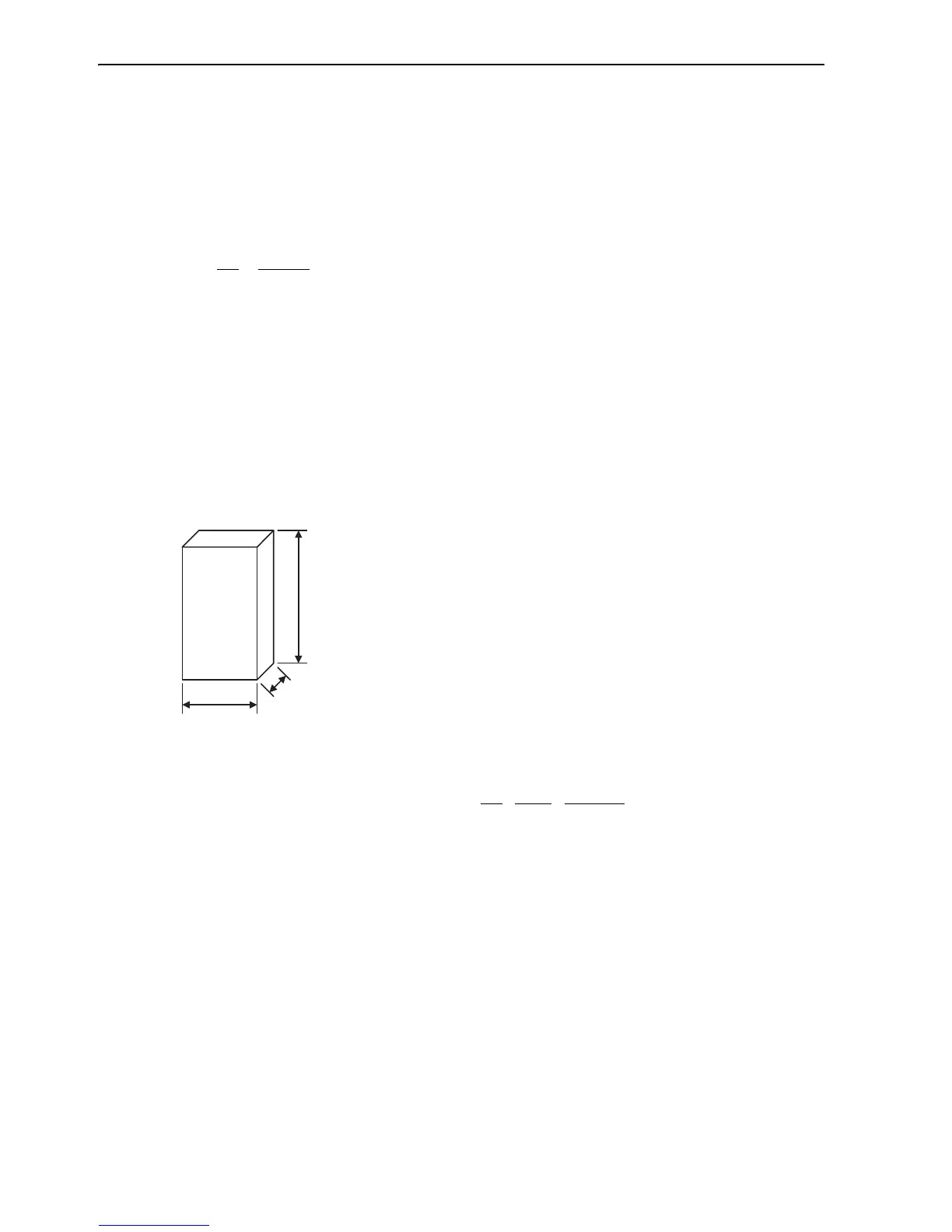
•A: Effective radiation area of the control panel (m
2
)
*
∗ Radiation available area of the control panel surface area (Exclude the surface which contacts other object)
<Example>
Allowable Watt Data Loss for a Control Panel with a Stirring Fan
•Effective radiation area of the control panel: A=1.0155 (m
2
)
(Exclude the base area because control panel is type of putting on the floor.)
•Calorific value in the control panel: P=60 (W)
•Temperature rise value in the control panel: ∆T= = = =9.8 (°C)
This example is correct design because ∆T is equal to 9.8 (°C).
 Loading...


