4 Specifications and External Dimensions for Σ-V-SD Drivers
4.1.1 Specifications
4-2
4.1 Power Regeneration Converter
4.1.1 Specifications
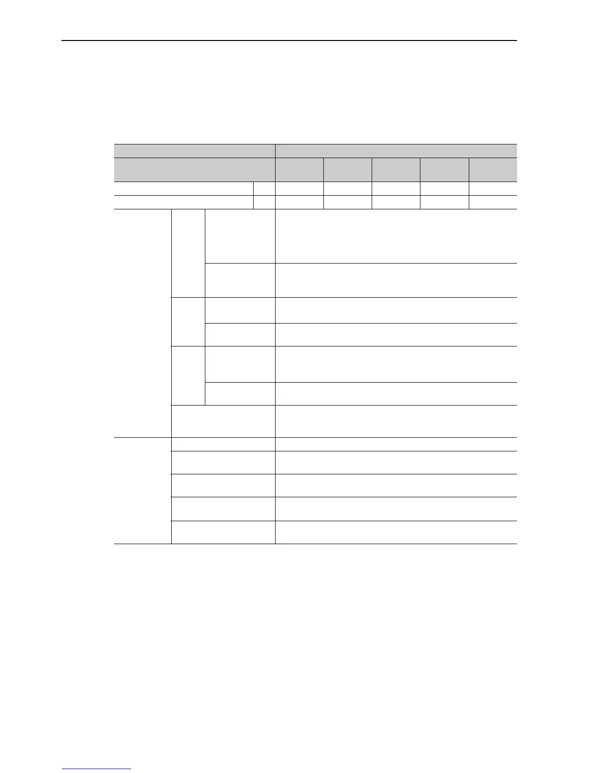
(1) Basic Specifications
∗ Available only for three-phase 200 VAC models.
Item Specifications
Model: CACP-JUA3,
CACP-JUD3
15 19 22
30
*
45
*
50% ED Rating kW 15 18.5 22 30 45
Continuous Rating kW 11 15 18.5 22 37
Basic
Specifications
Input
Power
Main Circuits
L1, L2, and L3
CACP-JUA3: Three-phase 200 to 230 V (50/60 Hz)
CACP-JUD3: Three-phase 380 to 480 V (50/60 Hz)
Allowable voltage fluctuation: +10% to -15%
Allowable frequency fluctuation: ±5%
Line voltage unbalance: 5% max.
Control Power
24 VDC
Allowable voltage fluctuation: ±15%
Output holding time: 100 ms min.
Output
Power
Main Circuit
Power Output +/
-
CACP-JUA3: 270 to 310 VDC +10 to -15%
CACP-JUD3: 520 to 650 VDC +10 to
-15%
Control Power
Output
24 VDC ±15% (connector pass current: 10 A)
I/O
Signals
Sequence I/O
Signals
Input signal: Emergency stop input signal
Output signal: Main circuit contactor ON output signal
Connections
between Axes
Local bus and absolute encoder battery
Maximum Number of
Connectable
SERVOPACKs
Differs in accordance with combinations of a power generation con-
verter, SERVOPACKs and motors. Refer to 2.1.3 Power Regeneration
Converter, SERVOPACK, and Motor.
Functions
Indications CHARGE (orange), ALARM (red), and READY (green)
Regeneration Control
Method
Power regeneration control (120-degree conduction)
Protective Functions
Main circuit fuse, overload, overvoltage, insufficient voltage, overcur-
rent, frequency error, heat sink overheating, etc.
Battery
The battery for the absolute encoder must be provided by the user.
For details, refer to 2.3.3 Absolute Encoder Battery.
Allowable Power Loss
Time
5 ms (at 70% load)
 Loading...


