7.2 SP20 BOARD
(1) SW1(RPG)
ON1
4
7
10
(Swl)
(Swl)
i==%’” rl
ON1 0 (=] 3 ()”
000
6
4 000
6
000
9
7 000
9
00
0 12 10 000
12
1 1
I
Simultaneoussingle axis
Sirnul taneous 3-axis
manua 1 pulse generator
manua 1 pulse generator
standard setting
oplional setting
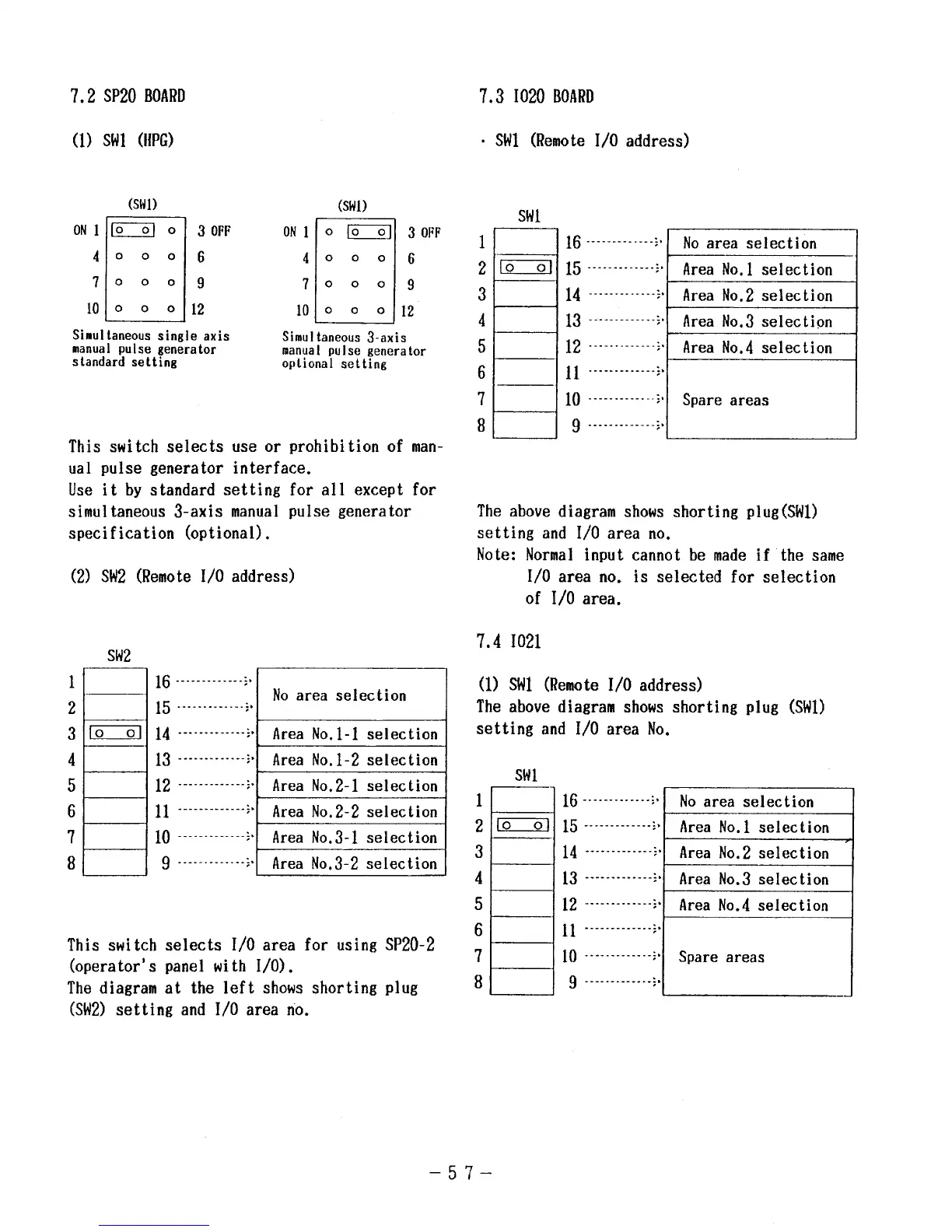
This switch selects use or prohibition of man-
ual pulse generator interface.
Use it by standard setting for all except for
simultaneous 3-axis manual pulse generator
specification (optional).
(2) SW2 (Remote 1/0 address)
SW2
1
--l
16 -------------~”
No area selection
2
15 “---”-------+’
I
31~ 14 -------------;, Area No.1-1 selection
4]
I 13 ..-... -...;.1 Area
No.I-Z selection I
I
I
1-
[
5 I I 12 -------------~”~Area No.2-1 selection]
61
I ~~ .......1 A
rea No.2-2 selection I
I
I
L
f
71
I lo .....-. -.--..1 Area Noe3-1 selection I
8 I I 9-------------:’
Area No.3-2 selection
This switch selects 1/0 area for using SP20-2
(operator’s panel with 1/0).
The diagram at the left shows shorting plug
(SW2)setting and 1/0 area no.
7.31020 BOARD
● SW1(Remote 1/0 address)
1
2
3
4
5
6
7
8
Swl
m
16-------------:$ No area selection
15 “-”””---”---”:”
Area No.1 selection
H
14 ------------+s Area No.2 selection
13------------+> Area No.3 selection
12------------+’ Area No.4 selection
~~ .........+.
10 ‘-----------~$ Spare areas
I
9 ---”-”-””--”+1
I
1 1 I
The above diagram shows shorting plug (SW1)
setting and 1/0 area no.
Note: Normal input cannot be made if the same
7.4
(1)
The
1/0 area no. is selected for selection
of 1/0 area.
1021
SWl (Remote 1/0 address)
above diagram shows shorting plug (SW1)
setting and 1/0 area No.
1
2
3
4
5
6
7
8
Swl
] 16------------:,1 No area selection
1
m 15--------””---:’
Area No.1 selection
i
14 --------’---~s
Area No.2 selection
13 --------”----:’
Area No.3 selection
12 “-””-”--”--””:’
Area No.4 selection
~~ ..........+.
10 -.-------....;.
spare areas
9 ----”------”-~”
–57–

 Loading...


