<5. Wiring>
46
IM01C25A01-01E
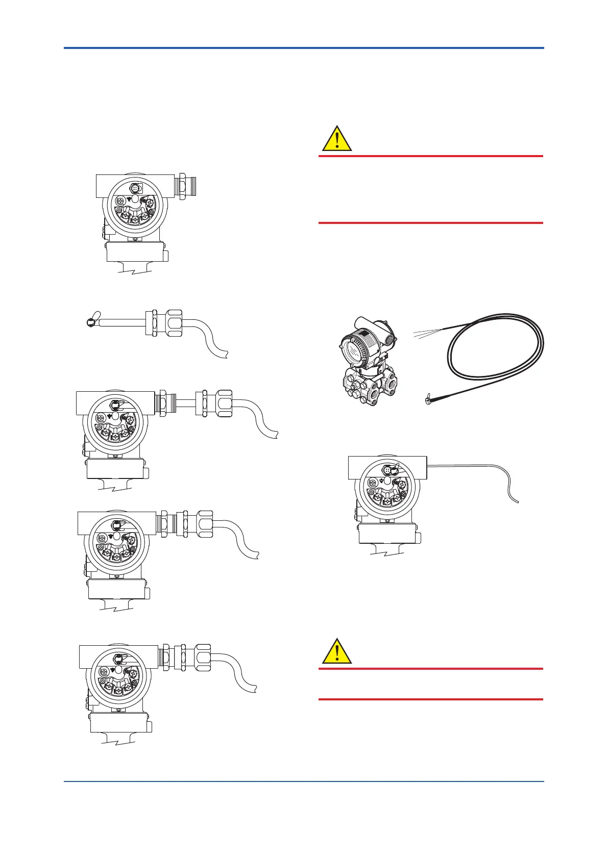
Procedure
(1)Disassemblethecablegland:loosentherunning
couplertoseparatethebacknutfromtheentry.
(2)Removetheprotectioncapoverthetransmitter
electricalconnectionandinstalltheentryonthe
electricalconnection.Notethatanon-hardening
sealantshouldbeappliedtothethreadsfora1/2NPT
connectionandagasketshouldbeusedforanM20
connection.
F0517.ai
(3)PasstheRTDcablethroughtherunningcouplerand
backnutassembly.
F0518.ai
(4)InserttheRTDcableandrmlyplugitsconnectorinto
theconnectingportinthetransmitter'sterminalbox.
F0519.ai
(5)Aligntherunningcouplerontheentry.
F0520.ai
(6)Turntherunningcoupleruntilthesealintheentry
comesintocontactwiththeRTDcable.
F0521.ai
(7)Rotatetherunningcoupleranotherhalfturnto
securelytightenthesealontheRTDcable.
(8)Useaprotectionconduit,ifnecessary.
Inthiscase,insertthecablethroughtheconduitand
attachittotheBacknut.
CAUTION
Afterthecableissecuredasexplainedabove,donot
tightentherunningcoupleranyfurther;todosocould
damagetheRTDconnection.
Donotpullthecableorsubjectittoexcessive
mechanicalshock.
5.4.2 Connecting Shielded Cable for Con-
duit Use (External temperature input
code: -B, -C, and -D)
• RTDconnectioncomponents:EJXmultivariable
transmitterandRTDcable
Procedure
(1)RemovetheprotectioncapprotectingtheRTD
electricalconnectionandinserttheRTDcable.
F0523.ai
(2)Removethecapprotectingtheconnectingport.Then
inserttheRTDcableandrmlyplugtheconnector
intotheconnectingportinthetransmitter'sterminal
box.
(3)Insertthecablethroughtheconduitandattachitto
theRTDelectricalconnection.
CAUTION
Donotpullthecableorsubjectittoexcessive
mechanicalshock.
 Loading...


