<2. Installation >
2-6
IM 11M10A01-01E
2.4 Wiring
WARNING
Secure all wiring behind the panel, to protect the ends of the wires and the terminals if the cable is pulled.
2.4.1 PowerWiring
CAUTION
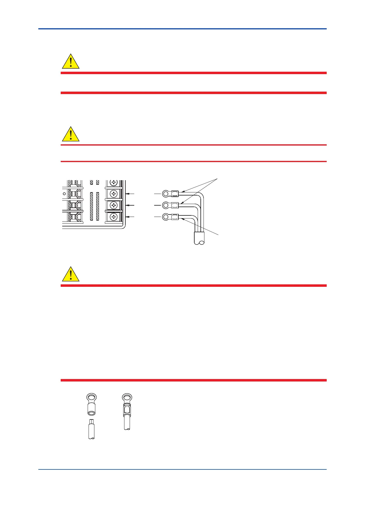
Connect 100 V AC power to terminals 15 and 16 on the rear terminal strip. Ground terminal 17.
15
14
16
32
33
34
1735
Power cable
Ground
Figure2.6 Powerwiring
WARNING
• Tominimizethepossibilityofelectricalshock,ensurethatpowersourceisobeforewiring
power cable.
• Tominimizethepossibilityofre,use600Vratedheavyvinylinsulatedcable(JISC3307)
or similar for power wiring.
• Before applying power, connect the ground terminal to a ground connection with ground
resistance of 100 or less.
• Use crimp-on terminals (4 mm screw) and heat-shrink insulating sleeves on power and
ground wiring. (See Fig. 2.7 for illustration of crimp-on terminals).
• The power connection to this instrument should have a switch in it, for safety reasons.
• When wiring, be careful not to drop strands of wire or wire clippings into the instrument.
After
crimping
Before
crimping
Fig.2.7 Crimp-onterminals
4th Edition : Oct. 23, 2019-00
 Loading...


