Appendix
App.-2
IM 11M10A01-01E
2.Installation
The sampling unit is a desktop type and should be installed on a stand near the sampling point.
Note the following when installing the unit.
CAUTION
The unit should be installed in places where:
• Ambienttemperatureisintherangeof0to40Candtemperatureuctuationsareminimal.
• Mechanical vibration is negligible.
• Adequatespaceforinspectionandmaintenance,suchasreplacinglterelement,is
secured.
• The unit should be securely mounted on a stand to prevent its dropping.
• No exposure to rain or water is allowed.
Procedure:
(1) Feed sampling tubing from the sampling point through a stop valve to the sample gas inlet,
GAS IN, with care not to produce gas leakage. The piping connection of the sample gas
inlet is Rc1/4. Use an appropriate joint for this connection.
(2) Feed gas vent tubing from the sampling outlet, GAS OUT, with care not to produce gas
leakage. The piping connection of the sampling gas outlet is Rc1/4. Use an appropriate joint
for his connection.
(3) Insert a power cable to the power connector of the sampling unit.
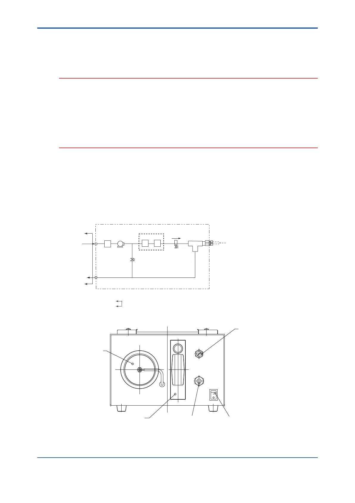
SENSOR
0.5l/min
AP101E.eps
F2 F3
FM1
V1
F1 PU1
GAS IN
GAS OUT
Note: Piping connection: Rc1/4
: Provided by customer
Figure1. PipingDiagram
AP102.Eeps
Activated Carbon
Filters: F2 + F3
Flowmeter: FM1
Sensor Connector, 8 mm O.D.
Switch
Needle Valve: V1
Figure2. SamplingUnit
4th Edition : Oct. 23, 2019-00
 Loading...


