Appendix
App.-6
IM 11M10A01-01E
2.SupplyingtheCalibrationGas
Take the following steps to supply the calibration gas.
(1) MountanOX100Seriessensortotheneedlevalveassemblybyinserting70to80mmof
thesensorandscrewingdownthelocknutrmlywithngers.Thelocknutshouldbenger
tight only and do not use a wrench for tightening.
(2) Turn the pressure regulating handle of the needle valve assembly’s regulator
counterclockwise completely.
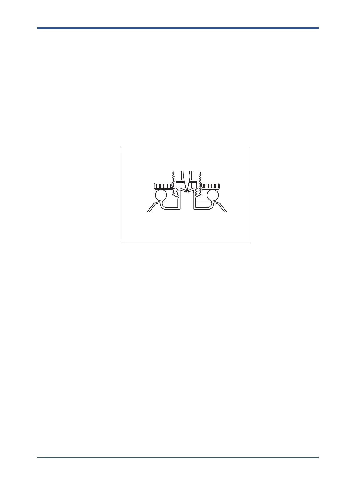
(3) Turn the handle of the needle valve clockwise until it can no longer turn so that the needle
tip pokes into the gas cylinder (See Figure 3).
(4) Turn the handle of the needle valve counterclockwise to the position shown in Figure 1.
(5) Turn the pressure regulating handle of the regulator gradually in a clockwise direction to set
the pressure at approximately 0.05 MPa. This allows the calibration gas to be supplied to
the sensor for calibration.
AP201E-3.eps
Figure 3
3.StoppingSupplyingtheCalibrationGas
Take the following steps to stop supplying the calibration gas.
(1) Turn the handle of the needle valve clockwise until it meets resistance.
(2) Turn the pressure regulating handle of the regulator counterclockwise completely.
4th Edition : Oct. 23, 2019-00
 Loading...


