3. INSTALLATION AND WIRING
IM 12B6C2-E-H
3-1. Installation and dimensions
3-1-1. Installation site
As the transmitter is a rain-tight type it can
be installed outdoors as well as indoors. It
should, however, be installed as close as
possible to the sensors avoiding long cable
lengths between sensors and transmitter.
The certified version can be installed in
Zone 1.
Select an installation site where:
- mechanical vibrations and shocks are
negligible;
- no relay/power switches are in the direct
environment;
- the transmitter is not mounted in direct
sunlight and severe weather conditions;
- maintenance activities are possible (no
corrosive atmospheres).
The ambient temperature and humidity
should be within the limits of the specifica-
tions .
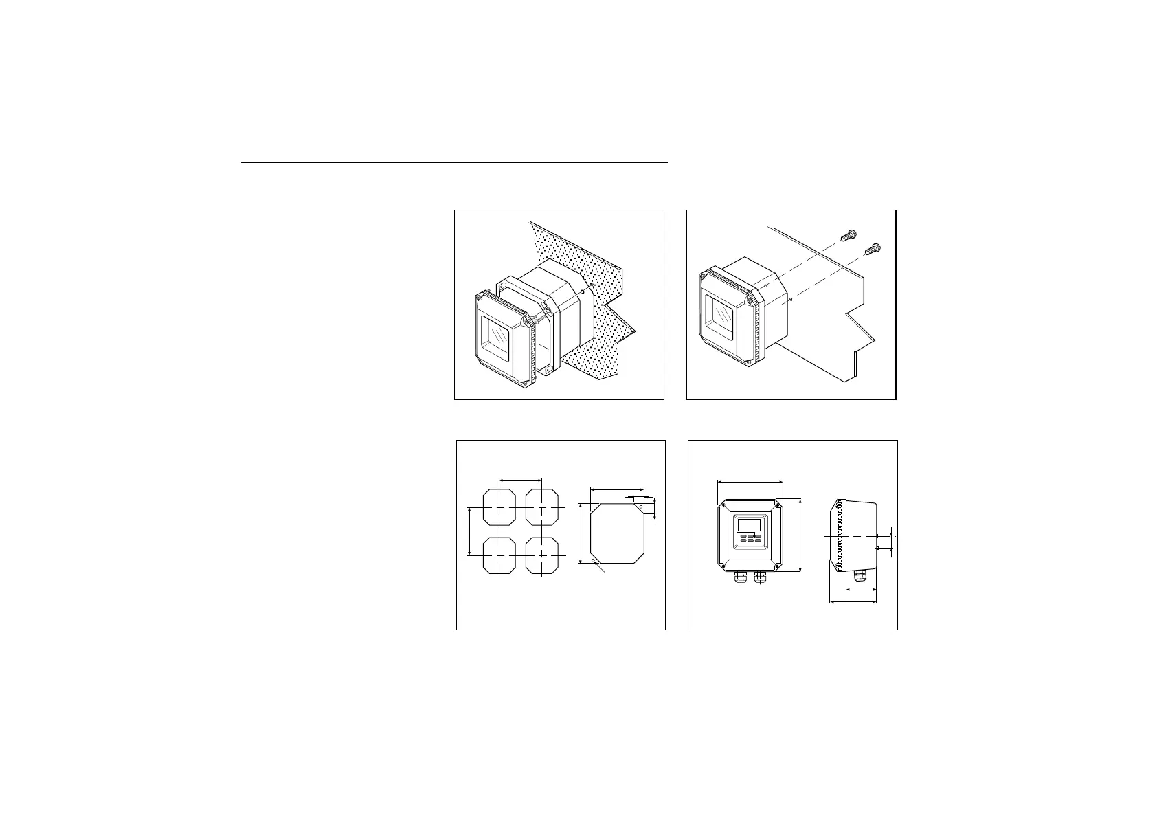
3-1-2. Mounting methods
The EXA PH200 transmitter has universal
mounting possibilities:
- panel mounting using selftapping screws
- surface mounting on a plate (by bolts
from the back)
- wall mounting on a bracket (e.g. thick
brick wall);
- pipe mounting using a bracket on a hori-
zontal or vertical pipe (maximum diame-
ter 50 mm).
4
Panel mounting
Surface mounting
DimensionsCut-outs for panel mounting
2 x M6 (Screws)
Unit: mm (“)Unit: mm (“)
154 (6.06`)
162 (6.4)
180 (7)
77
115 (4.5)
30 1.2)
30 (1.18)
172(6.77)
2x ø4
min. 203 (8)
min. 229 (9)

 Loading...


