IM 12B6C2-E-H
3-2. Wiring of sensors
3-2-1. General precautions
Generally, transmission of signals from pH
sensors is at a very low voltage and high
impedance level. Thus a lot of care must be
taken to avoid interference. Before connec-
ting sensor cables to the transmitter make
sure that next conditions are met:
– the sensor cables are not mounted in
tracks together with high voltage and or
power switching cables
– only standard coaxial electrode cables or
extension cable are used
– the transmitter is mounted within the dis-
tance of the sensor cables (max. 10 m)
– the setup is kept flexible for easy inser-
tion and retraction of the sensors in the
fitting.
3-2-2. Additional precautions for instal-
lations in hazardous areas
Make sure that the total of capacitances and
inductances connected to the input termi-
nals of the EXA PH200 do not exceed the
limits given in the certificate.
This sets a limit to the cable and extensions
used.
– Grounding:
• If the sensors are mounted in a grounded
fitting, the external earth connection on
the left hand side of the transmitter must
be connected to "protective" earth.
• If the sensors are mounted in a fitting iso-
lated to ground, it is recommended (not
required) to connect the earth connection
on the left hand side of the transmitter to
"protective" earth.
– The intrinsic safe version of the EXA
PH200 instrument can be erected in
Zone 1.
– The sensors can be installed in Zone 0 or
Zone 1 if a safety barrier according to the
limits given in the system certificate is
used.
3-2-3. Liquid earth
In all circumstances, the sensor side of the
measuring loop must be grounded to the
measuring liquid. The EXA PH200 uses
advanced differential high impedance input
circuits. This technique calls for a grounding
to the liquid. In addition to that the sensor
checking circuits also use the liquid earth for
measurement of impedance of the sensors.
All Yokogawa fittings have provisions for this
connection. It is usually called liquid earth in
all our manuals.
A separate connection should be made to
the terminal numbered 14 in all cases to get
a proper and stable measuring loop.
3-2-4. Access to terminal and cable
entry
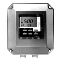
1. To access terminals remove the front
cover of the EXA PH200 by releasing the
4 captive screws.
2. Thread the sensor cables into the con-
nection space and connect the cables to
the terminals as indicated in the wiring
diagram. Make sure all connections are
firm and do not touch each other.
3. Screw the gland securely and tighten it to
keep out moisture. DO NOT use a
wrench to tighten the nut.
4. The optional hose connection is used to
guide the cables coming from an immer-
sion fitting through a protective plastic
tubing to the transmitter.
6
 Loading...


