<10. EXPLOSION-PROTECTED TYPE INSTRUMENTS>
10-8
IM 01R01B02-00E-E 12th edition October 01, 2014 -00
All Rights Reserved. Copyright © 2003, Rota Yokogawa
Rota Yokogawa
D-79664 Wehr
WT-MAG Mat. No. 16-8040
Serial No, xxxxxxxx
Ex ia IIC T6 Gb
IECEx PTB 12.0020
Ui=30V Ii=101mA Pi=1.4W
Li=0.15mH Ci=4.16nF
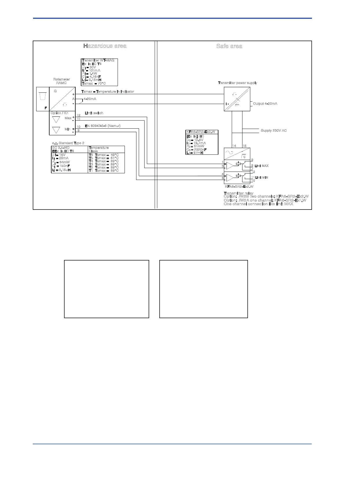
10.4.2 Installation
Fig. 10.2 Ex-Version according IECEx (Option /ES1) with electronic transmitter, power supply and
limit switches with transmitter relay
15
4
6
3
1
14
12
10
11
8
7
9
12
11
10
9
I -
I +
L/+N/-
O -
O+
Output 4-20mA
U
F
G
RAMC
A
Supply 230V AC
KFA6-SR2-Ex2.W
Option: /W2B two channels: KFA6-SR2-Ex2.W
Transmitter relay
Limit MIN
Limit MAX
Option / Kn
Rotameter
4-20mA
Max
Min
Limit switch
EN 60947-5-6 (Namur)
One channel connection like limit MAX
I = 101mA
P = 1.4W
C = 4.16nF
U = 30V
L = 0.15mH
Ex ia IIC T6
Gb
IECEx PTB 12.0020
Tamax = 70°C
Tamax = Temperature in indicator
C = 150nF
EEx ia IIC T6
L = 0.15uH
SC 3.5-NO
P = 64mW
I = 25mA
U = 16V
Temperature
Class
Transmitter power supply
Option: /W2A one channel: KF A6-SR2-Ex1.W
KFA6-SR2-Ex2.W
IECEx PTB 11.0031X
IECEx PTB 11.0091X
Transmitter WT-MAG
T4 Tamax = 89°C
T3 Tamax = 89°C
T2 Tamax = 89°C
T1 Tamax = 89°C
T5 Tamax = 61°C
T6 Tamax = 49°C
-
+
-
+
-
+
~ ~
+
-
+
-
i
i
i
i
i
i
i
i
i
F6.EPS
i
C = 2320nF
I = 19.1mA
P = 51mW
U = 10.6V
L = 97mH
[Ex ia]) IIC
o
o
o
o
o
Hazardous area
Safe area
e.g. Standard Type 2
10.4.3 Marking
Name plates of electronic transmitter :
 Loading...