<A2. SAFETY INSTRUMENTED SYSTEMS INSTALLATION>
A2-1
IM 01R01B02-00E-E 12th edition October 01, 2014 -00
All Rights Reserved. Copyright © 2003, Rota Yokogawa
The contents of this appendix are cited from exida.com safety manual on the Rotameter RAMC Flowmeter
specically observed for the safety transmitter purpose. When using the RAMC for Safety Instrumented
Systems (SIS) application, the instructions and procedures in this section must be strictly followed in order
to preserve the meter for that safety level.
A2.1 Scope and Purpose
This document provides an overview of the user responsibilities for installation and operation of the Rota
Yokogawa RAMC variable area ow meter in order to maintain the designed safety level. Items that will be
addressed are proof testing, repair and replacement of the ow meter, reliability data, lifetime, environmental
and application limits, and parameter settings.
A2.2 Using RAMC for a SIS Application
A2.2.1 Safety Function
Suitable for use in Safety Instrumented Systems are the versions listed in table A2.1 only. The safety related
data listed in this manual does not apply to other versions of RAMC.
Table A2.1 Versions of RAMC suitable for Safety Instrumented Systems
[V1] RAMC with inductive limit switch(es) – Options /K1 to /K3 and /K6 to /K10
[V2] RAMC with 4-20mA output – Code –E / -H
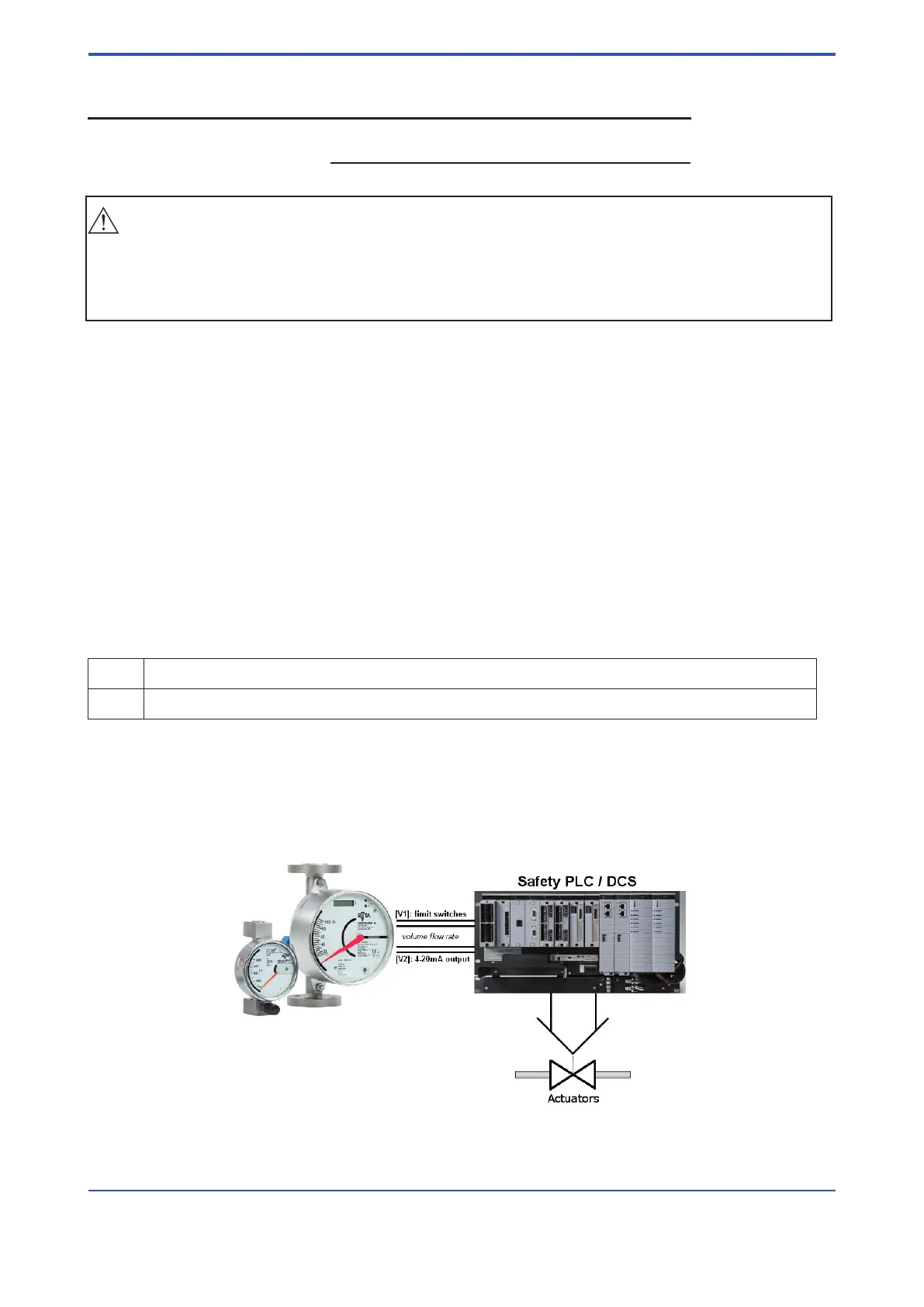
This variable area ow meter is intended for use as a volume ow monitoring component in a Safety
Instrumented System. It has either inductive limit switches [V1] or a 4-20mA analog output [V2]. The ow
meter may be used with the limit switches or the 4–20mA output to feed signals to a logic solver that is part
of the safety instrumented function (SIF) as shown in Figure A2.1. The fault annunciation mechanism is a trip
of one of the limit switches [V1] or an out of range analog current [V2]. In order to take credit for the automatic
diagnostics in the ow meter, this annunciation mechanism must be connected.
Figure A2.1 Example Safety Instrumented Function
APPENDIX 2. Safety Instrumented
Systems Installation

 Loading...