<A2. SAFETY INSTRUMENTED SYSTEMS INSTALLATION>
A2-2
IM 01R01B02-00E-E 12th edition October 01, 2014 -00
All Rights Reserved. Copyright © 2003, Rota Yokogawa
A2.2.2 Diagnostic Response Time
[V2]: The ow meter will report an internal failure within 5 minutes of fault occurrence for oat blocking
detection (time can be set to 15 minutes) and immediate for all other errors.
[V1]: The limit switch will go to its safe fail state immediately.
A2.2.3 Setup
Normally a setup of the ow meter is not required. During installation the ow meter can be setup with
engineering unit parameters [V2]. This is typically done with a handheld device. These parameters must be
veried during the installation to insure that the correct parameters are in the ow meter. Engineering range
parameters can be veried by reading these parameters from the optional local display or by checking actual
calibration of the ow meter.
Calibration of the ow meter must be done after parameters are set.
A2.2.4 Proof Testing
The objective of proof testing is to detect failures within the ow meter that are not detected by the
diagnostics of the ow meter. Of main concern are undetected failures that prevent the safety instrumented
function from performing its intended function.
The frequency of the proof tests (or the proof test interval) is to be determined in the reliability calculations
for the safety instrumented functions for which the ow meter is applied. The actual proof tests must be
performed more frequently or as frequently as specied in the calculation in order to maintain required safety
integrity of the safety instrumented function.
The following tests need to be specically executed when a proof test is performed. The results of the proof
test need to be documented and this documentation should be part of a plant safety management system.
Failures that are detected should be reported to Yokogawa.
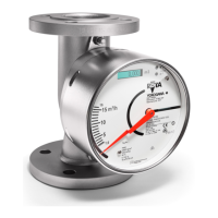
a) Proof test for variable area ow meter RAMC with inductive limit switches [V1]
Step Action
1 Take appropriate action to avoid a false trip
2 Inspect the device for any visible damage, corrosion or contamination
3 Force the variable area ow meter RAMC to reach a dened “MAX” threshold value and verify that
the inductive limit switch goes into the safe state.
4 Force the variable area ow meter RAMC to reach a dened “MIN” threshold value and verify that
the inductive limit switch goes into the safe state
5 Restore the loop to full operation
6 Restore normal operation
b) Proof test for variable area ow meter RAMC with 4-20mA output [V2]
Step Action
1 Bypass the safety PLC or take other appropriate action to avoid a false trip
2 Perform a two-point calibration of the variable area ow meter RAMC
3 Force the variable area ow meter RAMC to go to the high alarm current output and verify that the
analog current reaches that value. Note: it is only possible to set RAMC to the high alarm current
mode via HART communication!
This tests for compliance voltage problems such as a low loop power supply voltage or increased wiring resistance.
This also tests for other possible failures.
4 Force variable area ow meter RAMC to go to the low alarm current output and verify that the ana-
log current reaches that value.
This tests for possible quiescent current related failures
5 Restore the loop to full operation
6 Remove the bypass from the safety PLC or otherwise restore normal operation
 Loading...


