<7. HART-COMMUNICATION>
7- 2
IM 01R01B02-00E-E 12th edition October 01, 2014 -00
All Rights Reserved. Copyright © 2003, Rota Yokogawa
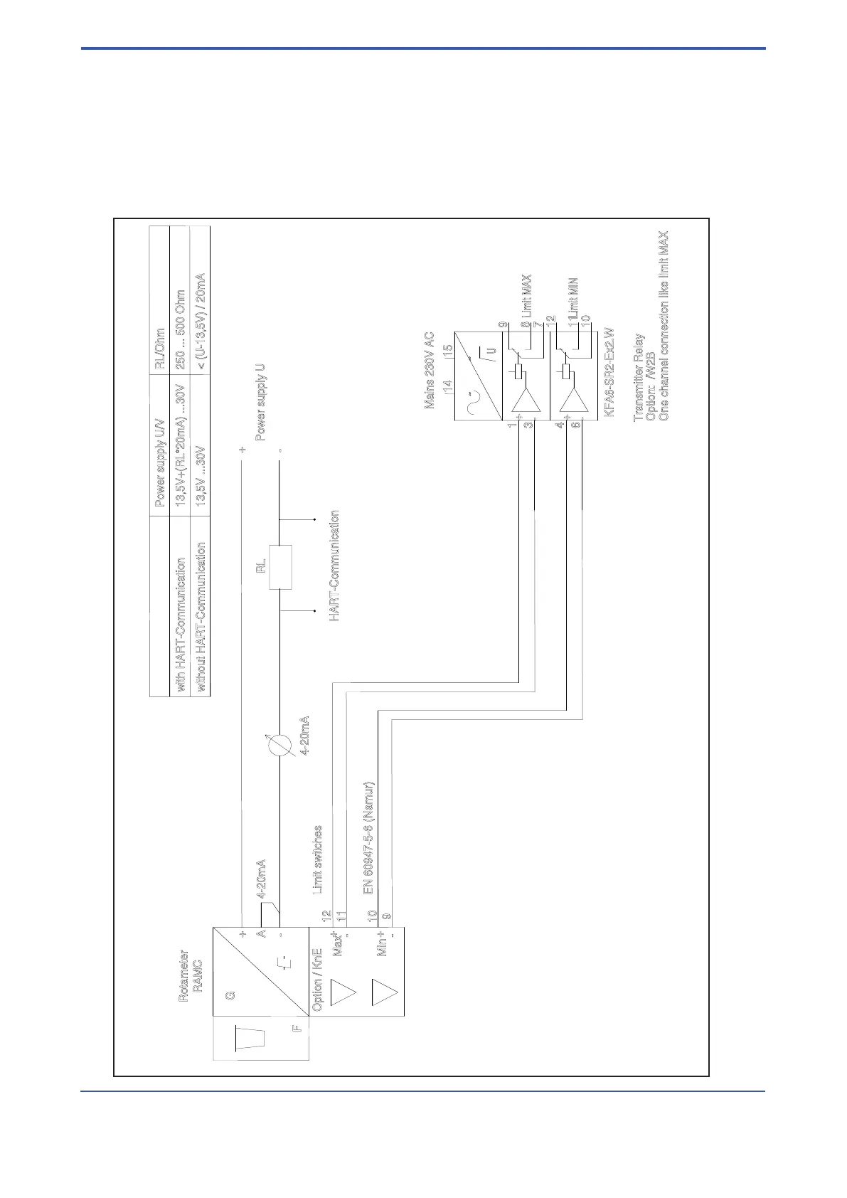
7.2 Connection
The connection is carried out in accordance with below gure. Please note, that the load resistor must have a
value between 250 and 500Ω .
The minimum power supply is 13.5V + (RL*20mA) ; RL = load resistor
The maximum power supply is 30V.
As connection cable a protected twisted cable pair is recommended.
15
4
6
3
1
14
12
10
11
8
7
9
U
F
G
RAMC
A
Power supply U
Mains 230V AC
KFA6-SR2-Ex2.W
Option: /W2B
Transmitter Relay
Limit MIN
Limit MAX
Option / KnE
Rotameter
4-20mA
Max
Min
12
11
10
9
Limit switches
EN 60947-5-6 (Namur)
One channel connection like limit MAX
4-20mA
RL
HART-Communication
with HART-Communication
without HART-Communication
Power supply U/V
RL/Ohm
13,5V+(RL*20mA) ...30V
13,5V ...30V
< (U-13,5V) / 20mA
250 ... 500 Ohm
-
+
-
+
-
+
-
+
~
~
+
-
+
-
F71.EPS
 Loading...