<10. EXPLOSION-PROTECTED TYPE INSTRUMENTS>
10-11
IM 01R01B02-00E-E 12th edition October 01, 2014 -00
All Rights Reserved. Copyright © 2003, Rota Yokogawa
Installation:
For installation see Control Drawings on page 10-13 and 10-14
- Installation should be in accordance with National Electrical Code, ANSI / NPFA70.
- For intrinsic safe application a safety barrier or FM approved power supply must be used which meet the
above mentioned entity parameters.
-
For non incendive application the general purpose equipment must be FM approved which non
eld wiring
which meet the above mentioned non incendive eld wiring parameters.
- The FM Approved Hand Held Communicator may be connected at any point in the loop between the
electronic transmitter and the Control Equipment
Maintenance and repair:
The instrument modication or part replacements by other than authorized representative of Rota Yokogawa
is prohibited and will void the approval of FM Approvals.
Marking:
Name plates of electronic transmitter :
IS-Cl. I, Div. 1, GP. A, B, C, D T6
per dwg. 8160190
NI-Cl. I, Div. 2, GP. A, B, C, D T6
per dwg. 8160191
Cl. I, Zone 0, AEx ia IIC T6
Vmax=30V Imax=100mA Pmax=1.4W
Ci=40nF Li=150µH Ta=-25°C to 70°C
Rota Yokogawa
D-79664 Wehr
WT-MAG Mat. No. 16-8040
Serial No, 0711001
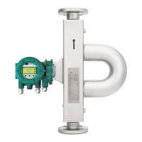
10.7 Intrinsically safe FM / CSA (USA + Canada) components
(/FS1, /CS1)
10.7.1 Electronic transmitter (/FS1 for USA, /CS1 for Canada)
Technical data:
Certicate : No. 3027471
Applicable Standards :
FM3600, FM3610, FM3611, FM3810
C22.2 No. 157, C22.2 No. 213
Type of protection :
intrinsic safe Cl. I, Div. 1, GP. A, B, C, D T6
intrinsic safe Cl. I, Zone 0, AEx ia IIC T6
non incendive Cl. I, Div. 2, GP. A, B, C, D T6
Ambient temperature : -25°C ... +70°C
Maximum Entity and Non incendive Field Wiring Parameters :
Vi = 30 V
Ii = 100 mA
Pi = 1.4 W
Ci = 40 nF
Li = 150 µH
 Loading...