<3. INSTALLATION>
3-6
IM 01R01B02-00E-E 12th edition October 01, 2014 -00
All Rights Reserved. Copyright © 2003, Rota Yokogawa
15
4
6
3
1
14
12
10
11
8
7
9
U
F
G
RAMC
A
Power supply U
Mains 230V AC
KFA6-SR2-Ex2.W
Option: /W2B
Transmitter Relay
Limit MIN
Limit MAX
Option / Kn
Rotameter
4-20mA
Max
Min
12
11
10
9
Limit switches
EN 60947-5-6 (Namur)
One channel connection like limit MAX
4-20mA
RL
HART-Communication
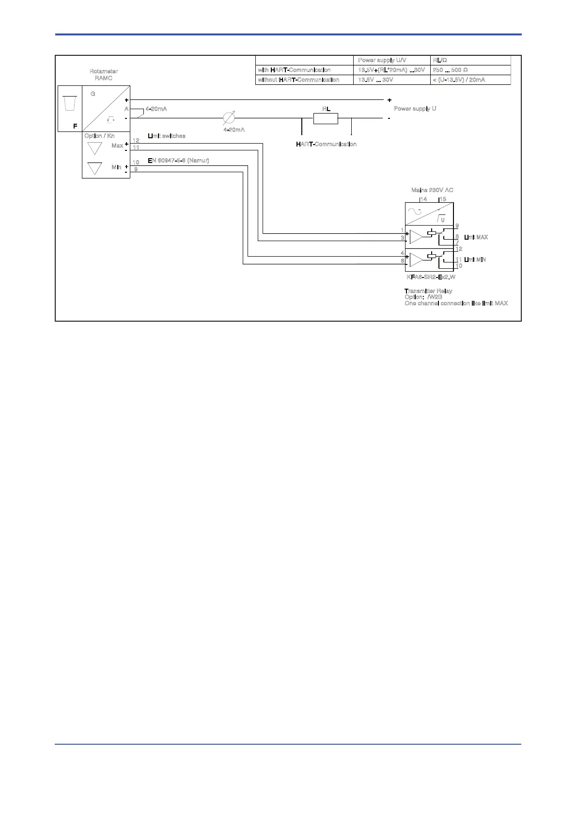
with HART-Communication
without HART-Communication
Power supply U/V RL/Ω
13.5V+(RL*20mA) ...30V
13.5V ... 30V < (U-13.5V) / 20mA
250 ... 500 Ω
-
+
-
+
-
+
-
+
~ ~
+
-
+
-
F4.EPS
Fig. 3-7 RAMC 2-wire unit with HART-communication, with limit switches and transmitter relay
 Loading...