7
All Rights Reserved. Copyright © 2012, Yokogawa Electric Corporation
GS 04L51B01-01EN
Nov. 10, 2015-00
HARDWARE SPECIFICATIONS
(MAINUNIT)
Display
Displayunit*:
GX10:5.7-inchTFTcolorLCD(640×480dots)
GX20:12.1-inchTFTcolorLCD(800×600dots)
* Asmallnumberofmissingorsteady-onLCD
pixelsandminorvariationsinbrightness
uniformityisanormaldisplaycharacteristicand
notamalfunction.
Touchscreen:
4 wire resistive touch screen
Construction
• Mounting:Flushpanelmounting(onavertical
plane)
• Mountingangle:Inclinedbackwardupto30
degreesfromahorizontalplane.Leftandright
horizontal
• Panelthickness:2to26mm
• Material;
Case: Metal plate
Bezel and display cover: Polycarbonate
• Color;
Case: Smoke blue
Bezel: Charcoal grey light
• Frontpanel:Wateranddustproof:Complieswith
IEC529-IP65andNEMANo.250TYPE4(except
ExternalIcingTest),exceptforside-by-side
mounting
• Externaldimensions:
Wheninstallingmodules
GX10:144(W)×144(H)×255(D)mm
GX20:288(W)×288(H)×220(D)mm
Whenuninstallingmodules
GX10:144(W)×144(H)×174(D)mm
GX20:288(W)×288(H)×169(D)mm
(D:depthfromthepanelmountingplane)
• Weight:
GX10:Approx.2.1kg,GX20:Approx.6.0kg
(excludingmodules)
PowerSupply
• Ratedsupplyvoltage:100to240VAC
• Allowablepowersupplyvoltagerange:90to132,
180to264VAC
• Ratedpowersupplyfrequency:50/60Hz
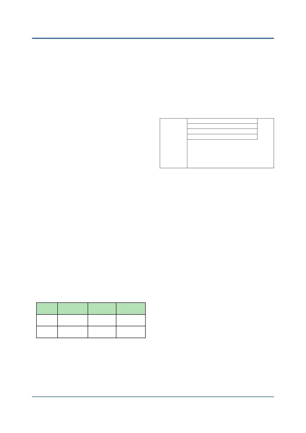
• Powerconsumption:
Supply
voltage
LCDbacklight
off
Normal
operation
Maximum
100VAC GX10:16VA
GX20:28VA
GX10:20VA
GX20:34VA
GX10:48VA
GX20:90VA
240VAC GX10:24VA
GX20:38VA
GX10:30VA
GX20:45VA
GX10:60VA
GX20:110VA
* ThefollowingcombinationsareassumedforLCD
backlightoffandnormaloperation.
GX10:1AImodule,1DOmodule,1DImodule
GX20:5AImodules,4DOmodules,1DImodule
• Modulepowersupplyvoltage:Thetotalallowable
powerconsumptionofrespectivemodulesisup
to6WintheGX10andupto20WintheGX20.
• Allowableinterruptiontime:Lessthan1cycleof
thepowersupplyfrequency
Isolation
• Insulationresistance:BetweentheEthernet,
RS-422/485, and each insulation terminals and
earth:20MΩorgreaterat500VDC
• Withstandvoltage:
Betweenthepowerterminalandearth:3000V
ACat50/60Hzforoneminute
Between the contact output terminal and earth:
3000VACat50/60Hzforoneminute
Between the input/output modules and earth:
DependsonthespecicationofI/Omodule.
• Grounding:Besuretosetalowgrounding
resistance.
• Isolation:
Power terminal
The circuits divided by lines are insulated mutually.
Internal circuit
Ethernet port
RS-422/485 terminal
Input and output module terminal
Input and output module internal circuit
Earth (PE) terminal
RS-232 terminal
SD card slot
USB port
SafetyandEMCStandards
• CSA:CSA22.2No.61010-1,installationcategory
II
*1
, pollution degree 2
*2
,andCSA-C22.2NO.
61010-2-030-12
• UL:UL61010-1,UL61010-2-030(CSANRTL/C)
• CE:
EMC directive
EN61326-1compliance,ClassATable2
EN61000-3-2 compliance
EN61000-3-3 compliance
EN55011ClassAGroup1
Low voltage directive
EN61010-1, EN 61010-2-030
InstallationcategoryII
*1
Pollution degree 2
*2
Measurement category
*3
• EMCRegulatoryArrangementinAustraliaand
New Zealand (RCM): EN55011 compliance,
ClassAGroup1
• KCmarking:Electromagneticwaveinterference
prevention standard, electromagnetic wave
protection standard compliance
*1 Installationcategory(overvoltagecategory)II:
Describesanumberwhichdenesatransient
overvoltage condition.
Impliestheregulationforimpulsewithstand
voltage.
“II”appliestoelectricalequipmentwhich
issuppliedfromthexedinstallationlikea
distribution board.
*2 Pollutiondegree2:
Describesthedegreetowhichasolid,liquid,
or gas which deteriorates dielectric strength or
surfaceresistivityisadhering.
“2”appliestonormalindooratmosphere.
Normally, only non-conductive pollution occurs.
*3 Measurementcategory:Dependsonthe
specicationofeachmodules
 Loading...
