● Required straight pipe lengths and recommendations (2)
D: Nominal diameter of vortex owmeter (mm)
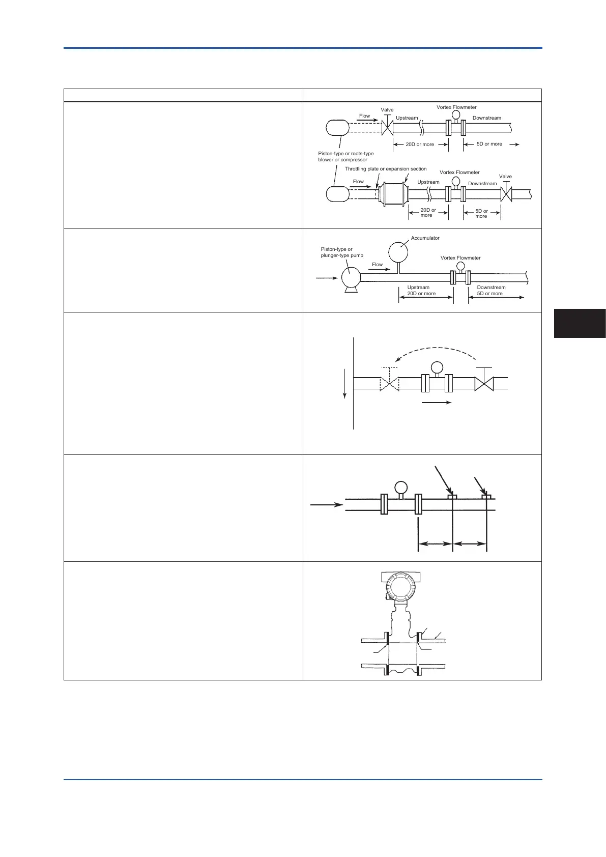
Description Figure
● Fluid vibration
Fluid vibration may occur in a gas line or high-pressure liquid
line (approximately 1 MPa or more) that uses a piston-type or
roots-type blower or compressor. In these cases, install the vortex
owmeter on the downstream side of the valve at a distance of 20D
or more, and ensure a length of 5D or more on the downstream
side of the owmeter. If the piping design requires that a valve be
installed on the downstream side of the vortex owmeter, install
a vibration damping device such as throttling plate or expansion
section on the upstream side of the vortex owmeter.
Vortex Flowmeter
Vortex Flowmeter
Upstream
Upstream
Downstream
Downstream
Flow
Valve
Valve
Flow
Piston-type or roots-type
blower or compressor
Throttling plate or expansion section
20D or
more
5D or
more
20D or more
5D or more
● Installing near a pump
If a piston-type or plunger-type pump is used, install an
accumulator on the upstream side of the vortex owmeter to
reduce uid vibration in the piping.
Vortex Flowmeter
Accumulator
Flow
Piston-type or
plunger-type pump
Upstream
20D or more
Downstream
5D or more
●Eect of pulsation pressure due to T-type piping
If pulsation pressure occurs due to T-type piping, install a valve on
the upstream side of the vortex owmeter.
Example: As shown in the gure, when the ow rate of A is zero
because V1 is closed, pulsation pressure is detected when B is
owing, which causes the zero point of the meter to uctuate. To
prevent this from occurring, change the valve installation location
to V1'.
Note: In case of the Reduced Bore Type, moisture may be
remained upstream of the owmeter. Drain it appropriately.
Relocating
Valve (Off)
A
Flow
V1’ V1
Vortex Flowmeter
● Pressure and temperature taps
When temperature/pressure compensation is to be performed,
install a pressure tap on the downstream side of the vortex
owmeter at a distance of 2D to 7D.
Then install a temperature tap on the downstream side of the
pressure tap at a distance of 1D to 2D.
When using a temperature tap only, install it on the downstream
side of the vortex owmeter at a distance of 3D to 9D.
Temperature tap
Upstream
2 to 7D 1 to 2D
Vortex Flowmeter
Flow
● Mounting gasket
Avoid mounting gaskets that protrude into the pipe line, as this
may cause inaccurate readings.
Use gaskets with bolt holes to prevent protrusion into the piping
line. When using a spiral gasket (without bolt holes), conrm the
size with the gasket-manufacturer, as standard items may not be
used for certain ange ratings.
Flange of adjacent pipe
Adjacent pipe
Make sure gasket does
not protrude
<3. Installation>
13
IM 01F07A01-01EN
Installation
3
 Loading...


