5-2 IM 760401-01E
4. Selecting the Measurement Mode
Select the measurement mode by pressing the VOLTAGE (MODE) key after having
pressed the SHIFT key so that the SHIFT indicator is lit. For more details, refer to
section 4.1, “Selecting the Measurement Mode.”
Explanation
Continuous Maximum Allowable Input
• Voltage
Up to peak voltage of 1.5 kV or RMS value of 1.0 kV, whichever is less.
• Current
•5 mA to 200 mA range (2.5 mA to 100 mA range if the crest factor is set to 6)
(WT210 only)
Up to peak current of 30 A or RMS value of 20 A, whichever is less.
• 0.5 A to 20 A range (0.25 A to 10 A range if the crest factor is set to 6) (common
to WT210 and WT230)
Up to peak current of 100 A or RMS value of 30 A, whichever is less.
• External sensor input (common to WT210 and WT230)
Peak value of up to five times the measurement range.
Maximum Reading, Unit, and Unit Prefix
• Maximum reading: 99999 (when the number of displayed digits is 5) for voltage,
current and power
• Units: V (voltage), A (current), W (power)
• Prefix: m, k, or M
Selecting the Display Function
The following selections are available.
• V: voltage will be displayed
• A: current will be displayed
• W: active power will be displayed
Selecting the Input Element
The type of input element which can be selected depends on the model number.
Make your selection after having verified your model number.
• 1/2/3: Displays the measurement values of element 1/2/3
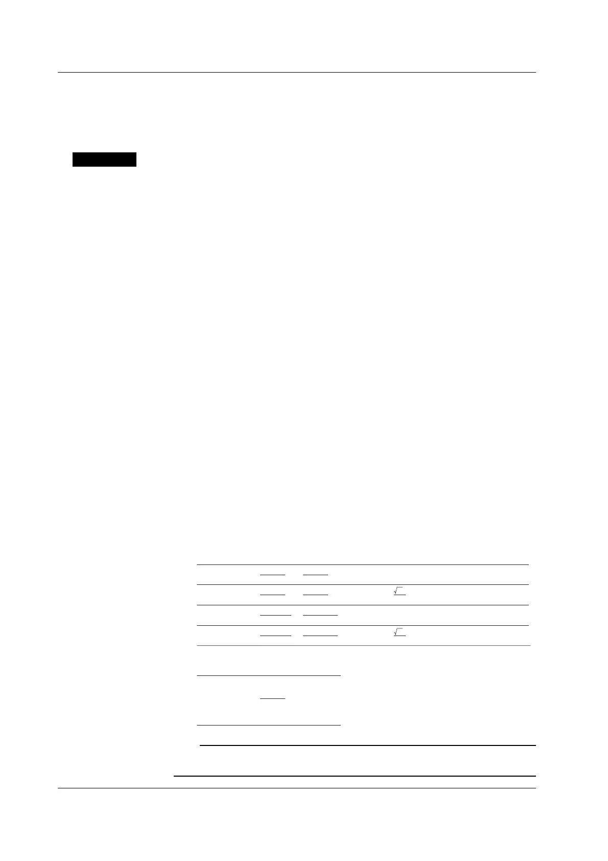
• Σ: Displays according to the wiring method, and is as follows.
ΣV ΣA
ΣW
1P3W
2
V1
+
V3
V1
+
V3
2
A1
+
A3
W1
+
W3
W1
+
W3
W1
+
W2
+
W3
W1
+
W3
2
3
V1
+
V2
+
V3
3
V1
+
V2
+
V3
V1A1
+
V3A3
V1
A1+
V2A2
+
V3A3
V1A1
+
V3A3
var1
+
var3
var1
+
var3
var1
+
var2
+
var3
var1
+
var3
V1
A1+
V2A2
+
V3A3
3P4W
3V3A
3P3W
2
A1
+
A3
2
3
3
3
A1
+
A2
+
A3
3
A1
+
A2
+
A3
(
)
3
(
)
ΣVA Σvar
ΣPF Σdeg
1P3W
3P4W
3V3A
3P3W
ΣW
ΣVA
cos
-1
ΣPF
Wiring method
Wiring method
Note
For Σ var computation, when the current leads the voltage, each var value is computed as a
negative value; when the current lags the voltage, the value is computed as a positive value.
5.1 Displaying Voltage, Current and Active Power

 Loading...


