S-6 IM 760401-01E
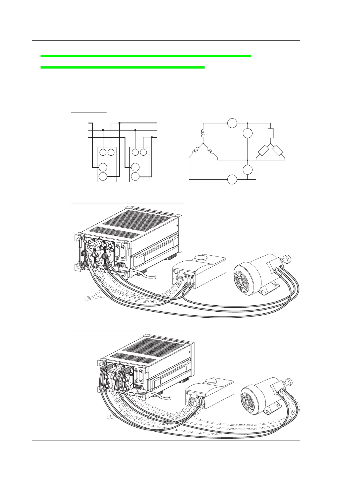
Wiring the Circuit on the Secondary Side of the Inverter
(Wiring a Three-Phase, Three-Wire System)
7.
Connect the voltage and current input terminals of input elements 1 and 3 on the
rear panel of the WT230 (760503) and the current measurement circuit and
voltage measurement circuit of the secondary side of the inverter and the motor.
Wiring Diagram
SOURCE
LOAD
SOURCE
(Inverter:
secondary side)
Load
(Motor)
±
C
±
A3
±
C
V(S)
U(R)
W(T)
V1
±
V
V3
V
U(R)
V(S)
W(T)
Input terminal
(ELEMENT 3)
Input terminal
(ELEMENT 1)
C
±
±
V
C
±
±
V
A1
V: VOLTAGE terminal
C: CURRENT terminal
Wiring Example of a Current Measurement Circuit
WT230
Inverter Motor
To SOURCE
Wiring Example of a Voltage Measurement Circuit
WT230
Inverter Motor
To SOURCE
Wiring the Circuit

 Loading...


