S-10 IM 760401-01E
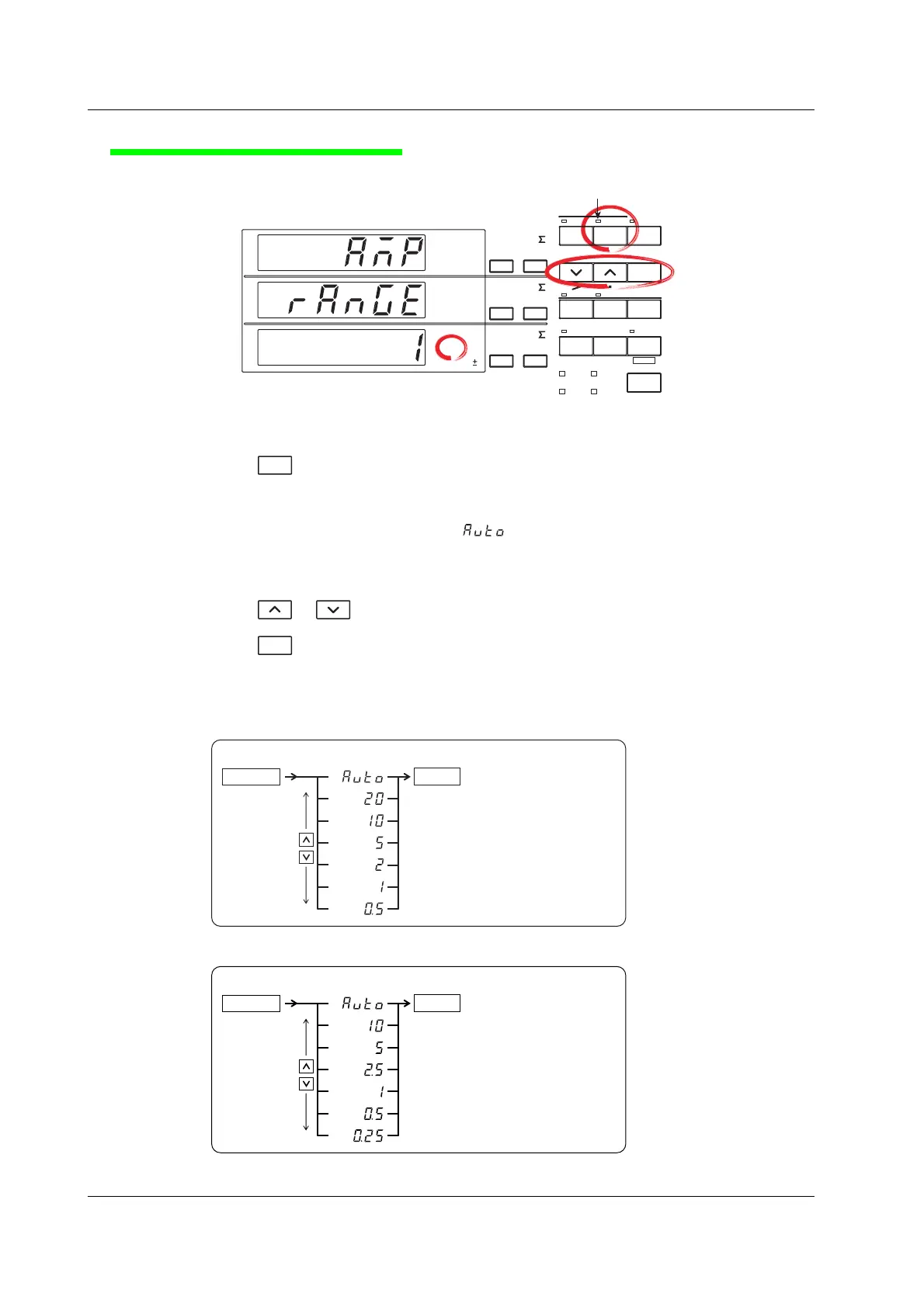
Selecting the Current Range
AUTO indicator for current range
A
B
C
FUNCTION
ELEMENT
1
m
V
k
A
V
TIME
ar
deg
h
h
VA
MW
m
VPF
k
A
MW
m
VHz
k
A
MW
23
FUNCTION
ELEMENT
123
FUNCTION
ELEMENT
123
VOLTAGE
AUTO
MODE
CURRENT
AUTO
RANGE
MAX HOLD
TRIG
CAL
INTEGRATOR
INTEG SET
SHIFT
KEY LOCK
1P3W
3P3W
3P4W
3V3A
OUTPUT
HARMONICS
MEMORY
REMOTE
HOLD
ENTER
RESET
WIRING
START STOP
LOCAL
SETUP
%
AMP
RANGE
1
For a description of the other digital numbers and characters that are
displayed on the 7-se
ment LED of each display, see section 1.3.
4.
Press
CURRENT
.
The current range selection menu appears.
Display C shows the current range selection with blinking indication.
If the current range had been set to “ ” before this step (AUTO indicator for the
current range is illuminated), the current range that is automatically selected from the
measured current is displayed blinking.
5.
Press or to show the desired current range on display C.
6.
Press
ENTER
.
The current range is confirmed. Each display shows the measured values.
The following flow chart illustrates steps 4 to 6.
( Display C )
End of setting
More selections are displayed on
products with option /EX1 or /EX2.
For details, see section 4.6.
ENTER
6.4.
CURRENT
5.
When the crest factor is set to 3
ENTER
6.
( Display C )
4.
CURRENT
5.
More selections are displayed on
products with option /EX1 or /EX2.
For details, see section 4.6.
End of setting
When the crest factor is set to 6
Selecting the Measurement Range

 Loading...


